YSM40R_Mainte_E.pdf - 第63页
2-8 2 Daily maintenance items 1.1.1 V acuum level when nozzle is open T he table below shows the vacuum lev el measured when each nozzle is open. T he values might differ slightly depending on the air source and operatin…
2-7
2
Daily maintenance items
n
RS head
The following is the description of RS head with Type 7203A nozzle as an example.
n
NOTE
See "1.1.1 Vacuum level when nozzle is open" in this chapter for nozzle other than Type 7203A.
e
1
Attach the nozzle.
Press the emergency stop button and attach
Type 7203A nozzles to heads on selected
table to be checked. When the machine
has a nozzle station, press the [Nozzle
Change] button to change the nozzles.
54206-N9-00
2
Release the "Emergency Stop"
status.
n
NOTE
Perform the RS head vacuum check when the servo is
ON.
3
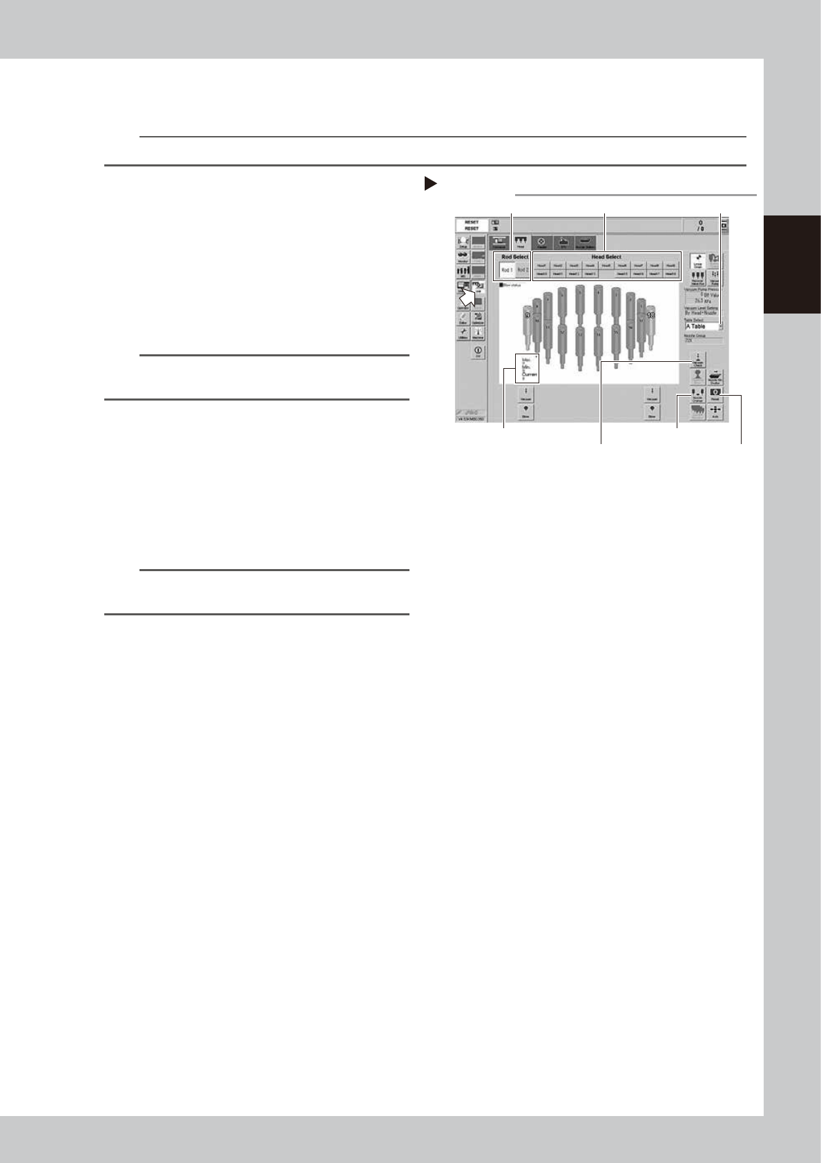
Reset the numerical figure.
1. Open the [Unit] - [Head] tab screen.
Press the [Table selection] button and
select the table that has the head to be
checked.
2. Press the [Reset] button on the lower
right of the screen to reset the vacuum
level values.
n
NOTE
The negative pressure check of RS head can only be
performed per head individually.
4
Generate negative pressure.
1. Press the [Rod Select] button and select
any rod (Valve axis: spool up-down axis).
Either rod 1 or rod 2 can be selected.
2. If pressing the [Head Select] button to
select the head to be checked, the
rotary of the head unit starts rotating and
the selected head moves under the
selected rod.
3. If pressing the [Vacuum Check] button,
the vacuum pump is activated and the
selected head becomes negative
pressure. When this value starts rising,
wait 5 to 10 seconds and press the
[Vacuum Check] button again and set to
OFF.
5
Check the vacuum levels.
1. Check all "Max" values shown in red on
the vacuum pressure result. If this value is
200 or less then it is in normal range.
2. If higher than 200, then the nozzle hole
might be dirty or the filter clogging might
be detected. See "1.2 Nozzle cleaning"
or "2.6.1 Inspecting and replacing the air
filters" in Chapter 3 to Clean the nozzle or
replace the filter.
Step 1 to 4
[Nozzle Change] button
[Rod Select] button
[Head Select] button
[Reset] button
Table Selec button
RS head negative pressure generation
Vacuum pressure result
[Vacuum Check] button
2-8
2
Daily maintenance items
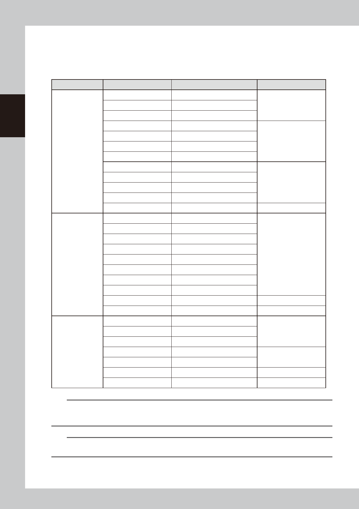
1.1.1 Vacuum level when nozzle is open
The table below shows the vacuum level measured when each nozzle is open.
The values might differ slightly depending on the air source and operating conditions. Use these values for
reference during maintenance.
n
Standard vacuum level when nozzle is open
Head Type Nozzle Standard value when nozzle is open Remarks
MU head
Type500A 180 or less
Standard nozzleType501A 120 or less
Type502A 75 or less
Type510A 180 or less
Narrow-pitch nozzle
Type511A 150 or less
Type512A 100 or less
Type513A 60 or less
Type503A/Type514A* 30 or less
Type504A/Type515A* 30 or less
Type506A/Type517A* 40 or less
Type507A/Type518A* 30 or less
No nozzle 30 or less
RS head
Type7201A 225 or less
Standard nozzle
Type7202A 220 or less
Type7203A 200 or less
Type7204A 150 or less
Type7205A 110 or less
Type7206A 110 or less
Type7207A 110 or less
Type7208A 110 or less
No nozzle** 100 or less
No nozzle/No filter 90 or less
FL head
Type601A 120 or less
Type602A 75 or less
Type603A* 30 or less
Type604A* 30 or less
With O-ring
Type605A* 30 or less
Type606A* 40 or less With V-notch
No nozzle 30 or less
n
NOTE
The nozzle hole of the nozzles marked by asterisk (*) is larger than that of other nozzles. So, if the vacuum levels of a
head using those nozzles marked by asterisk (*) or using no nozzle exceed the above standard values, the air path
(spline shaft, etc.) in the head might be clogged.
n
NOTE
**When the vacuum level does not get 100 or less while nozzle is detached from RS head unit, measure the vacuum
level by detaching the filter.
2-9
2
Daily maintenance items
1.2 Checking the nozzles visually
To visually check nozzles, remove each nozzle from the head or from the nozzle station. Also, YSM40R is
equipped with a maintenance mirror that can be used to visually check nozzles.
n
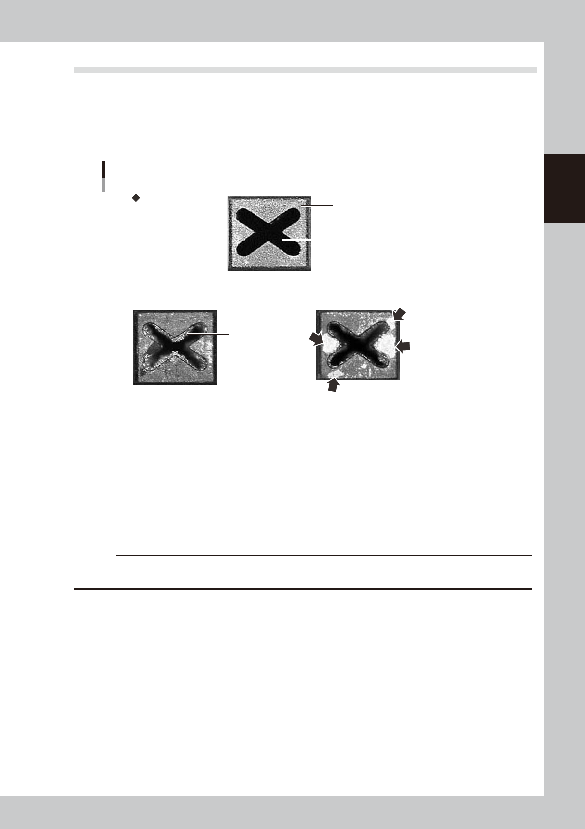
Points to check detached nozzles
Check the removed nozzles with a magnifying glass or similar tool. If solder or dust is adhering to the nozzle tip or
nozzle hole, then clean the nozzles.
Nozzle tip
Solder is adhering to
nozzle hole.
Solder is adhering to
nozzle tip (flat surface).
Nozzle hole
Checking the nozzle condition
No good: Nozzle is clogged No good: Shiny material on tip
Normal condition
53202-N9-00
n
Checking nozzles by detaching them from the head individually
1. Move the head to a position where the nozzles can be easily detached, then detach each nozzle manually.
2. After checking and cleaning the nozzle, reattach the nozzle to the head while making sure the head position and the
nozzle's orientation are correct.
n
Checking nozzles by detaching them from the nozzle station (option)
1. Return all nozzles in the nozzle station.
2. Press the [Nozzle Stn Shutter] button on the [Unit]-[Head] tab screen to be ready for detaching nozzles.
3. After checking and cleaning the nozzle, return nozzles to original positions and press the [Nozzle Stn Shutter] button.
c
CAUTION
Be sure to attach nozzles to the original head. When the nozzles were detached from the nozzle station (option), return
them in the original positions.