YSM40R_Mainte_E.pdf - 第197页
6-7 6 How to replace consumable parts 8 Reattach the belt. 1. T emporarily place the belt on the belt tensioner pulley. 2. Place the belt on the end pulley detached in Step 4 and mount it with the pulley shaft together w…
6-6
6
How to replace consumable parts
5
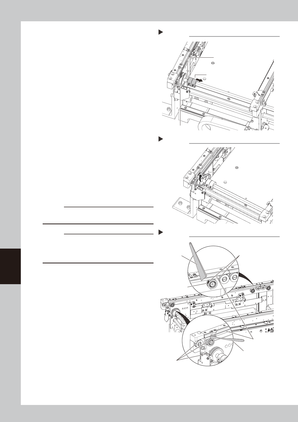
Separate the belt drive pulley from
the shaft.
1. Use a hex wrench (2.5) to loosen the
bolts on the coupling.
2. Disconnect the coupling from the drive
pulley to allow a gap through which the
belt can be taken out.
53610-N9-00
6
Detach the belt from the conveyor.
Detach the conveyor belt by taking it out
through the gap between the coupling and
the drive pulley.
53617-N9-00
7
Clean the guides and pulleys.
1. Use a vacuum assembly (option) to
suction the belt wear debris on the belt
guides and sensors, etc.
2. Use a plastic spatula or similar tool to
remove the belt wear debris adhering to
the outer peripheral surface of the
pulleys.
3. Use a brush or similar tool to remove the
belt wear debris caught in the belt
guides.
53618-N9-00
c
CAUTION
Use a plastic spatula and brush to avoid scratching the
pulleys and guides.
c
CAUTION
Do not use a solvent (IPA, etc.) unless the guides and
pulleys are excessively dirty. If using a solvent, be
careful not to spill the solvent on the bearing in the
pulleys during cleaning.
Loosening the coupling
Step 5
Take out the belt through this gap.
Coupling
Drive pulley
Detaching the conveyor belt
Step 6
Cleaning the guide and pulleys
Step 7
Spatula
(made of plastic)
Brush
Belt guides
Outer peripheral
surface of pulley
Outer peripheral surface
of pulley
Belt wear debris
sticking to pulley
6-7
6
How to replace consumable parts
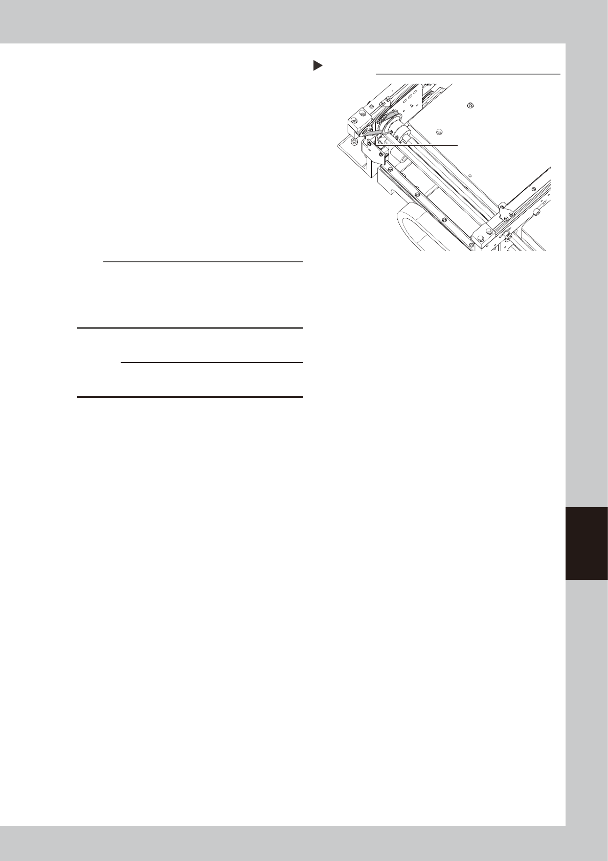
8
Reattach the belt.
1. Temporarily place the belt on the belt
tensioner pulley.
2. Place the belt on the end pulley
detached in Step 4 and mount it with the
pulley shaft together with the washer.
3. Connect the coupling to the drive pulley
and tighten the bolts.
4. Move the belt tensioner pulley to the
position marked in Step 4 and tighten the
bolt while applying tension.
5. If there is a slack in the belt, adjust the
position of the belt tensioner pulley to
apply proper tension.
n
NOTE
The specified conveyor belt tension for this machine is
as follows. Use a tension gauge to adjust the belt
tension as needed.
• Stage 1 : 260 to 320Hz
• Stage 2 : 180 to 220Hz
53611-N9-00
c
CAUTION
The tightening torque for the belt tensioner pulley is 5.5
N·m. Be careful not to overtighten.
9
Attach board clamp assembly.
1. Attach board clamp assembly to the
original position. Mount it by tightening 4
bolts with hex wrench (2.5).
2. Remove square cloth.
0
Return tape cutter duct to original
position.
Tension measurement point
Step 8
Tension measurement
point (outer side of
each lane
6-8
6
How to replace consumable parts
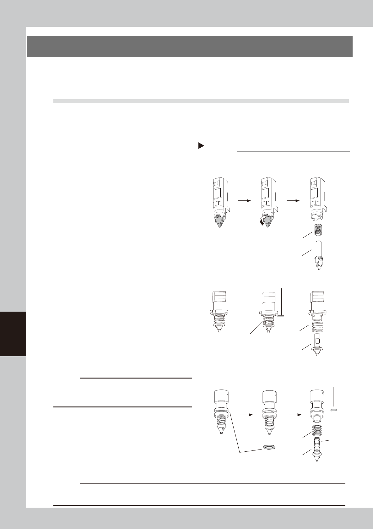
3. Replacing the nozzle tip
When the nozzle tip or O-ring is worn out due to long-term use, pickup and placement errors are likely
to occur. If the spring action of a nozzle is not smooth even after cleaning and lubricating the nozzle, the
internal spring may need to be replaced.
3.1 Replacing nozzle tip and spring
e
1
Detach the nozzle.
1. Press the emergency stop button and
then open the machine safety cover.
2. Turn off the carriage clamp switch to
detach carriage from mounter.
3. Detach relevant nozzle with leaf springs
manually.
2
Replace the nozzle tip and spring
(Type 50X Series nozzles).
1. Turn the nozzle tip 90 degrees while
pressing on it.
2. Detach nozzle tip by pulling it downward.
3. The internal spring comes out as the
nozzle tip is detached.
4. Replace the nozzle tip and/or spring.
5. Attach the nozzle in the reverse of the
above procedure.
53615-N9-00
3
Replace the nozzle tip and spring
(Type 720X Series nozzles).
1. Detach the O-ring from the nozzle. Use a
precision screwdriver if difficult to
detach.
2. Pull out the pin.
3. Replace the nozzle tip and/or spring.
4. Insert pin to mount nozzle tip aligning pin
with groove in nozzle tip.
5. Attach the O-ring. If the O-ring is loose or
worn out, replace it with a new one.
c
CAUTION
See each head unit on "2.1 Consumable parts" in
Chapter 1 to check that nozzle marking (example: 601A,
511A) on nozzle body matches type No. of nozzle tip.
4
Lubricate nozzle slide section.
See "1.2.1 Cleaning and lubricating nozzle
slide section" in Chapter 3 to lubricate nozzle
slide section.
5
Return nozzles to original position.
Return detached nozzles to the original
heads.
c
CAUTION
Make sure to return nozzles to original heads. If detached nozzles from nozzle station (option), return them to the
correct storage positions.
Replacing nozzle tip
Step 2, 3
■ Type 50X Series nozzles
Groove
Nozzle tip
Spring
Pull out the nozzle tip.
■ Type 720X Series nozzles
O-ring
Spring
Nozzle tip
Remove the O-ring.
Turn 90 degrees while
pressing on the nozzle tip.
Pull out pin.
■ Type 60X Series nozzles
Nozzle tip
Spring
Pull out pin.
Shorten spring.