YSM40R_Mainte_E.pdf - 第147页
3-77 3 Periodic maintenance items 7.2 Base section and others 7.2.1 Maintenance of the vacuum pumps YSM40R 4-beam type machine is equipped with 2 v acuum pumps and 2-beam type machine is equipped with 1 vacuum pump for p…
3-76
3
Periodic maintenance items
6
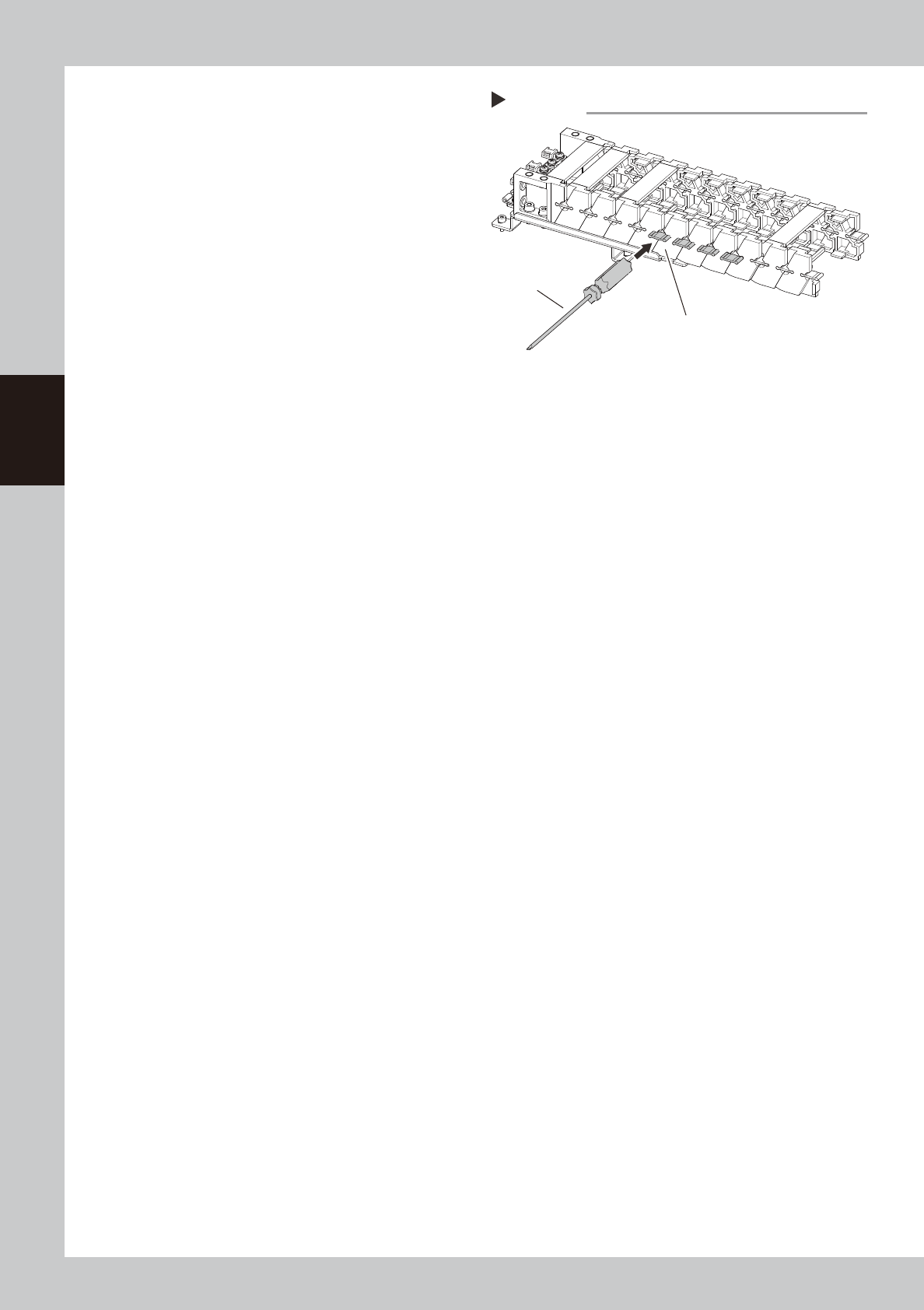
Attach the joint parts.
Insert the joint parts between the chain links.
After gently inserting, tapping them lightly
with a screwdriver handle or similar tool will
make it easier to fit them on.
533D5-N9-00
7
Attach the crossbars.
Align the crossbars with the snap-fit (clip)
and attach them in position.
Step 6
Fit on by tapping gently.
Use a screwdriver
handle, etc.
Attaching joint parts of Y-axis cable carrier
3-77
3
Periodic maintenance items
7.2 Base section and others
7.2.1 Maintenance of the vacuum pumps
YSM40R 4-beam type machine is equipped with 2 vacuum pumps and 2-beam type machine is equipped with
1 vacuum pump for part pickup. Though it may vary with the machine operating status, the packing and gaskets
should normally be replaced every 3 years (actual operating time of 8,000 hours after subtracting the machine
idle time).
n
Precautions when cleaning pump and replacing parts subject to wear
c
CAUTION
The inside of the pump is hot shortly after operation. Wait about 30 minutes after stopping operation and make sure the
pump has cooled down before starting the cleaning and replacement.
c
CAUTION
Wear dust-proof mask and gloves when replacing parts subject to wear. Otherwise you might inhale small particles of
worn parts or the hand might be injured.
c
CAUTION
The pump weighs more than 20 kg. Do not drop the pump to avoid injury to your feet and handle the pump carefully
not to hurt your back.
n
Required tools
1. Hex wrenches 5 mm, 3 mm
2. Torque limiting wrench With hexagonal socket having a width across flat of 5 mm (Tightening torque adjustable
to 8 N·m)
3. Phillips screwdriver No. 2
4. Torque limiting screwdriver No. 2 (Tightening torque adjustable to 0.55 and 3 N·m)
5. Cleaning solvent Ethyl alcohol or similar solvent not causing adverse effects on rubber components
6. Cleaning wipe Lint-free cleaning paper or cloth
7. Dust-proof mask and gloves
8. Oil-based marker pen
9. Grease (NSL grease)
n
Parts subject to wear (PUMP SPARE KIT: KLF-M86P0-00X) for 4-beam type machine
Part name Qty Recommended replacement interval Remarks
Cup packing 8 8000 hours
Gasket 8 8000 hours
FLAP 24 8000 hours Intake valve and exhaust valve
SHEET1 FLAP 8 8000 hours Intake valve backup
SHEET2 FLAP 8 8000 hours Exhaust valve backup
O-Ring 16 8000 hours Connecting pipe
n
NOTE
The vacuum pump maintenance kit (KLF-M86P0-00X) contains maintenance parts for servicing one 4-beam type
machine (2 pumps). Purchase KLF-M86P0-10X for 2-beam type machine (1 pump).
3-78
3
Periodic maintenance items
7.2.2 Detaching the pumps and making preparations
Check safety again before detaching the pumps.
Read "Precautions when cleaning the pump and replacing the parts subject to wear" on the preceding page and follow
the instructions to ensure the safety.
1
Prepare for work.
1. Detach the feeder exchange carriage
on the front of the machine.
2. Detach the tape cutter duct on the front
of the machine.
3. Power off the machine.
2
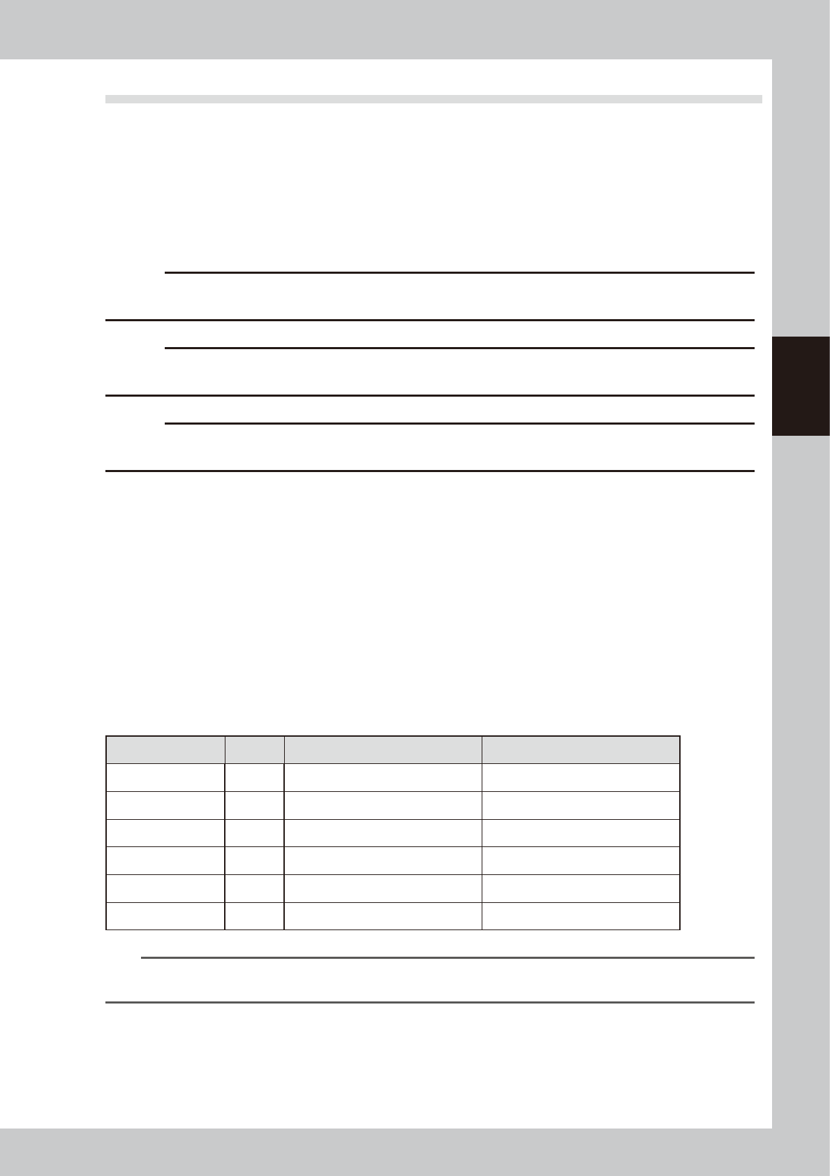
Detach the front cover.
1. Use a Phillips screwdriver to remove the
screws (6 pieces) that hold the machine
front cover and detach the cover.
2. Disconnect the ground wire located
behind the cover.
3. Detach the fan wiring connectors (2
places).
533A1-N9-00
c
CAUTION
When detaching the front cover, be careful not to
damage the harness wires, and pump and other
components in the machine.
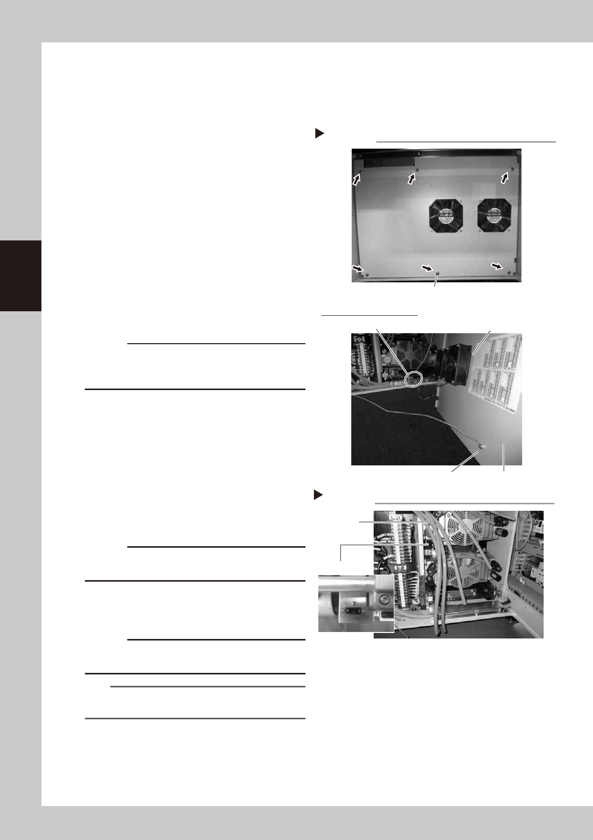
3
Disconnect the air hoses.
In the case of a 4-beam machine,
disconnect 4 air hoses each on the left and
right sides. In the case of a 2-beam
machine, disconnect only 4 air hoses on the
right side as viewed from the front.
533A3-N9-00
4
Detach the upper pump.
1. Disconnect the power connector and
ground wire from the side housing.
c
CAUTION
When disconnecting the ground wire, be careful not to
lose the washer.
2. Use a hex wrench (4) to remove 4 bolts
that mount the upper pump.
3. Pull out the upper pump to the front side.
c
CAUTION
The pump is heavy. When detaching the pump, be
careful not to drop it to avoid injury.
TIP
2-beam type machine (1 pump) is not equipped with
the upper pump.
Removing the machine front cover
Step 2
Fan
Fan wiring connector
Rear side of the front cover
Mounting screw
Ground wire
Front cover
Step 3, 4
Air hose
Disconnecting air hoses/power connecto
r
Power connector