YSM40R_Mainte_E.pdf - 第139页
3-69 3 Periodic maintenance items 6.1.2 Cleaning / lubricating upper par t of the nozzle shafts T he procedure for cleaning and lubricating the upper part of RS head nozzle shafts is described below . T he dedicated oil …
3-68
3
Periodic maintenance items
6. 2-year maintenance
This section describes 2-year maintenance items.
6.1 RS head
6.1.1 Clean/lubricate scissors gear
This section describes cleaning and lubricating the rotating axis (N-axis) in the rotary unit and the gears in the
rotating axis (R-axis) of each head all housed in the RS head
1
Prepare for work.
e
1. Remove all items sensitive to magnetic fields such as wristwatches and magnetic ID cards.
2. Press the emergency stop button and then open the machine safety cover.
3. Use the CLAMP ON/OFF switch to lower the feeder exchange carriage and detach it.
4. Move the head unit to a convenient position for maintenance work.
2
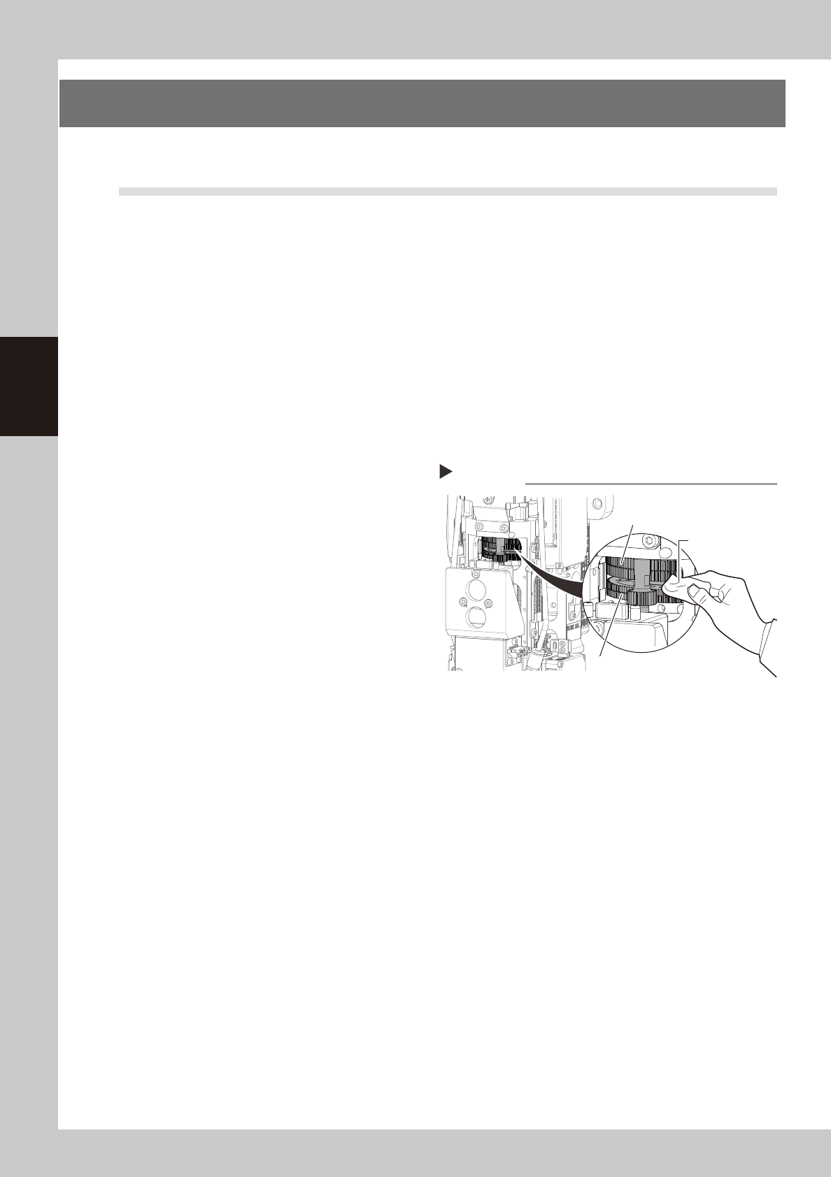
Clean the scissors gear.
While turning the scissors gear (R-axis), wipe
away the dirt and grime from the gears (2
scissors gears and the gear in front of them)
with a lint-free cloth.
53391-N9-00
3
Apply grease.
1. Apply the specified grease (LG2) by
hand or with a lint-free cloth to the
scissors gears of the N-axis and R-axis.
2. Turn the R-axis gear manually so that the
grease spreads into the entire gear.
4
Wipe off excess grease.
Wipe off excess grease with a lint-free cloth.
Step 2
Cleaning the scissors gear
Scissors gear (N-axis)
Scissors gear (R-axis)
Lint-free cloth
3-69
3
Periodic maintenance items
6.1.2 Cleaning
/
lubricating upper part of the nozzle shafts
The procedure for cleaning and lubricating the upper part of RS head nozzle shafts is described below. The
dedicated oil (KMB-M3855-00X) is required to lubricate the upper part of nozzle shafts.
1
Prepare for work.
e
1. Remove all items sensitive to magnetic fields such as wristwatches and magnetic ID cards.
2. (With nozzle station) Store all nozzles to nozzle station.
3. Press the emergency stop button and then open the machine safety cover.
4. Use the CLAMP ON/OFF switch to lower the feeder exchange carriage and detach it.
5. Move the head unit to a position where easy to perform the task.
n
NOTE
If the machine is not equipped with nozzle station, see "How to lower RS head/nozzle shafts" to lower Z-axis manually
before detaching nozzles.
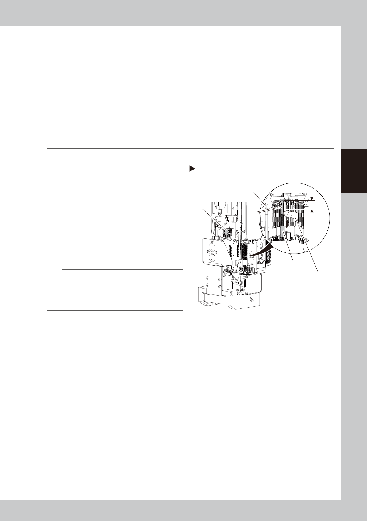
2
Clean the upper part of the shaft.
1. Use your finger to press down the nozzle
shaft spring of the head to be cleaned.
2. Wipe away dirt or grime from the upper
part of the nozzle shaft using a cotton
swab.
53393-N9-00
3
Apply grease.
Using a cotton swab dampened with the
specified oil (oil for upper part of shaft),
apply a thin uniform coat in approximately
a 10 mm range on the upper part of the
shaft.
n
NOTE
If the spring of the head to be lubricated is in a position
where difficult to lower, then turn the rotary unit by
referring to "How to lower RS head/nozzle shafts"
described earlier. The rotary unit can also be turned by
turning the R-axis gear by hand.
4
Clean and lubricate the other shafts
in the same way.
Clean and lubricate the other shafts using
the procedure in Steps 2 and 3.
Approx.
10 mm
Cleaning/lubricating nozzle shaft upper part
Step2-3
R-axis gear
Cotton swab
Press down the spring
with your finger.
Nozzle shaft
3-70
3
Periodic maintenance items
6.1.3 Replacing vacuum line Packing Assembly
The vacuum line for the RS head uses packings. The packings should generally be replaced every 2 years.
Replace these packings as an assembly.
1
Prepare for work.
e
1. Remove all items sensitive to magnetic fields such as wristwatches and magnetic ID cards.
2. Press the emergency stop button and then open the machine safety cover.
3. Use the CLAMP ON/OFF switch to lower the feeder exchange carriage and detach it.
4. Move the head unit to a convenient position for maintenance work. Place a square cloth under it.
5. Power off the machine.
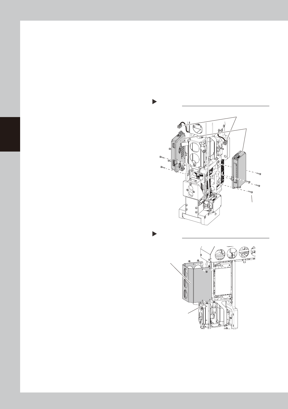
2
Detach the Z-axis units.
1. Detach the connectors from each X-axis
unit.
2. Use a hex wrench (2) to remove the
screws that mount each Z-axis unit and
detach the Z-axis units.
53395-N9-00
3
Detach the head cover.
Use a Phillips screwdriver to remove the
screws that holds head cover.
53396-N9-00
Detaching RS head Z-axis unit
Step 2
Connector
Z-axis unit
Z-axis unit mounting screw
Detaching RS head cover
Step 3
Head cover
Head cover mounting screw