YSM40R_Mainte_E.pdf - 第154页
3-84 3 Periodic maintenance items n Assembling the head cover 1 Replace the gasket. 1. Detach the gasket from the head cover and clean the head cover . 2. Blow air to dry the head cover and then fit a new gasket in the h…
3-83
3
Periodic maintenance items
7.2.4 Attaching the replaceable parts
n
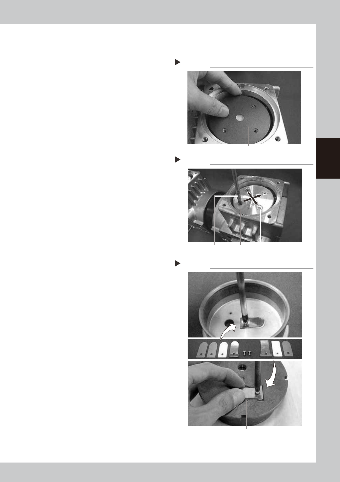
Attaching the cup packing and pressing plate
1
Place a new cup packing.
Place a new packing on the connecting
rod, with the sealing side facing down.
533B6-N9-00
2
Place the pressing plate.
Place the cleaned pressing plate on the cup
packing while aligning the mark with the
mark on the casing.
533B7-N9-00
3
Tighten the mounting screws.
1. Make sure the mark on the pressing plate
is aligned with the mark on the casing.
2. Use a torque limiting screwdriver to
tighten 4 screws (M5×L12) uniformly in a
diagonal order.
Tightening torque: 0.55 N·m
n
Attaching the cylinder parts
1
Reassemble the intake valve parts.
1. Place the two intake valves (FLAP) in the
cleaned cylinder and then place the
intake valve backup (SHEET1 FLAP) and
pressing plate on the intake valves.
2. Use a torque limiting screwdriver to
tighten the screw (M3×L5) to a torque of
0.55 N•m while being careful not to
make contact with the periphery of the
concave groove.
533B8-N9-00
2
Reassemble the exhaust valve parts.
1. Invert the cylinder, place the exhaust
valve on the cylinder, and place the
exhaust valve backup.
2. Place the pressing plate on the exhaust
valve, and use a torque limiting
screwdriver to tighten the screw (M3×L5)
while being careful not to make contact
with the periphery of the concave
groove.
Tightening torque: 0.55 N•m
3
Insert the cylinder.
Insert the cylinder in the cup packing
section while aligning the mark on the
cylinder with the mark on the casing.
Step 1
Placing a cup packing
Cup packing
Step 2, 3
Mounting the pressing plate
Mounting boltPressing plateTorque limiting screwdriver
Attaching cylinder parts
Tighten the screw so that the exhaust valve does not
make contact with the periphery of the groove.
Step 1
3-84
3
Periodic maintenance items
n
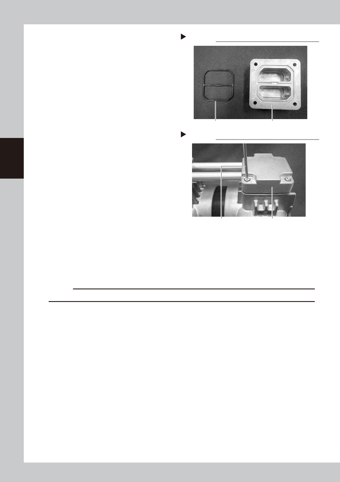
Assembling the head cover
1
Replace the gasket.
1. Detach the gasket from the head cover
and clean the head cover.
2. Blow air to dry the head cover and then
fit a new gasket in the head cover.
533B9-N9-00
2
Assemble the head covers.
1. Insert the connecting pipe into the head
covers.
2. Align the screw holes in the left and right
casings with the holes in the head
covers, and tighten 4 bolts (M6×L30)
each (total of 8 bolts) using a torque
limiting screwdriver.
Tightening torque: 8 N•m
533C1-N9-00
3
Reattach the panel.
Place the pump on its side and attach the
panel.
7.2.5 Attaching the pump
1
Attach the pump in its original position.
Attach the pump in reverse order of Step 3 to 5 in "7.2.2 Detaching the pumps and making
preparations" in this chapter.
c
CAUTION
Be careful not to drop the pump when attach the pump as it is heavy.
2
Attach the front cover.
1. Connect 2 connectors for fan.
2. Connect the ground wire behind the cover.
3. Tighten 6 mounting screws on front cover of machine front side with Phillips screwdriver.
3
Attach the duct on tape cutter that locates machine front.
Step 1
Replacing the gasket
Head coverGasket
Step 2
Attaching head covers
Head coverTorque limiting screwdriver
3-85
3
Periodic maintenance items
8. Others
8.1 Cleaning inside of nozzle shaft on RS head unit
When the vacuum level does not go down to 100 or less while nozzle is detached from RS head unit, replace with new
filter as a general. If vacuum level does not go down to the standard value even after replacing filter, The air path in
spline shaft may be dirty. In this case, it is required to clean the inside of nozzle shaft.
Note that clean 18 shafts of all heads as a rule even the vacuum level of one head does not go down to the standard
value as shaft inside of other heads may be dirty.
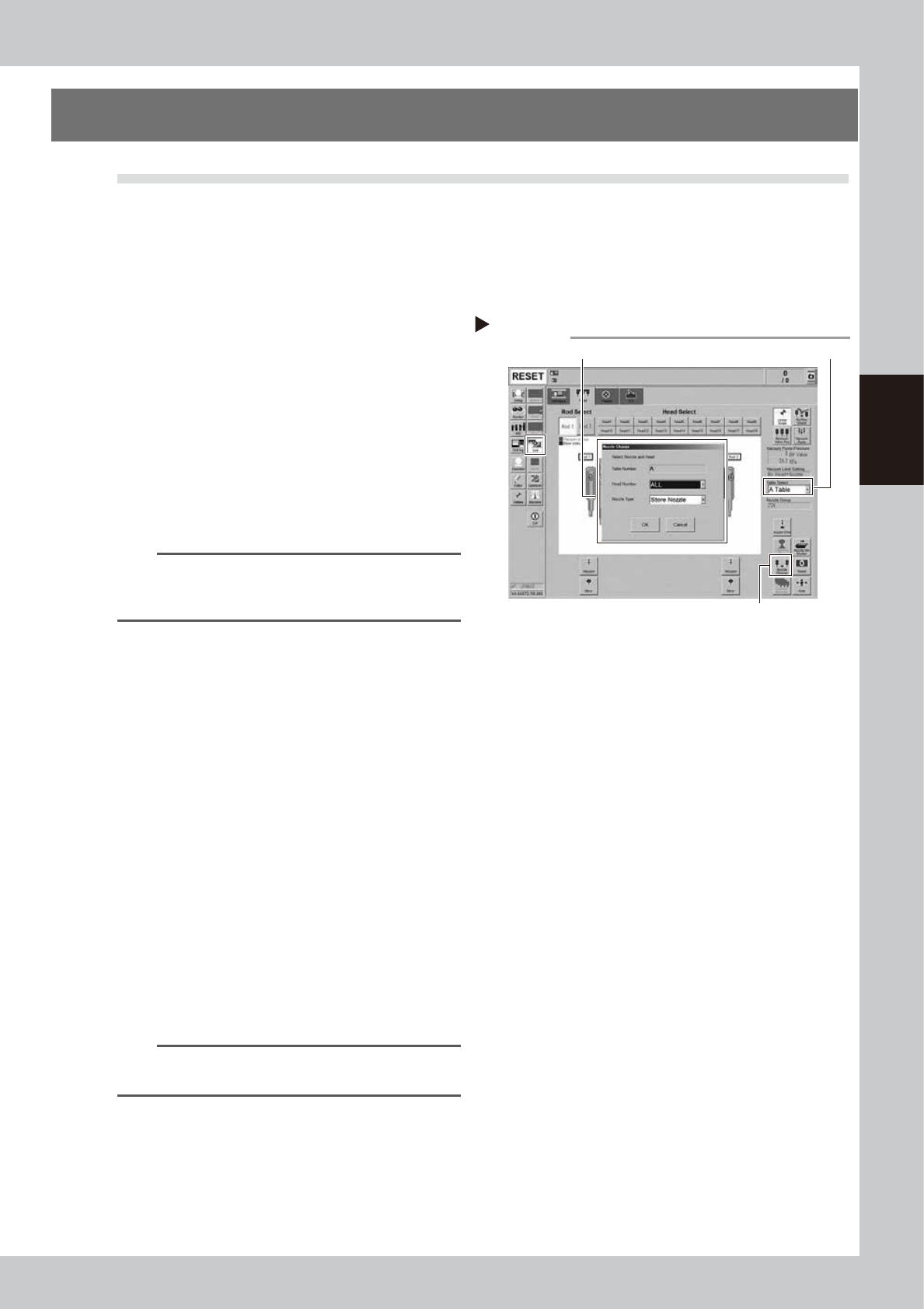
1
Store all nozzles to nozzle station.
1. Open the [Unit] - [Head] screen.
2. Select desired head unit from "Table
Select".
3. Press the [Nozzle Change] button.
4. Select "ALL" for "Head Number" and
select "Store Nozzle" for "Nozzle Type" on
the "Nozzle Change" screen.
5. Press the [OK] button to return all nozzles
to the nozzle station.
54305-N9-00
n
NOTE
If the machine is not equipped with a nozzle station,
press the emergency stop button and then detach the
nozzles manually.
2
Prepare for work.
e
1. Remove all items sensitive to magnetic
fields such as wristwatches and magnetic
ID cards.
2. Press the emergency stop button and
then open the machine safety cover.
3. Use the CLAMP ON/OFF switch to lower
the feeder exchange carriage and
detach it.
4. Move the head unit to convenient
position to work and place a square
cloth under the head unit.
3
Detach all filters.
See Step 3 in "2.6.1 Inspecting and replacing
the air filters" to detach all filters.
4
Clean and lubricate all spools.
See "3.2.3 Cleaning and lubricating the
vacuum selector (spool)" to clean and
lubricate all spools.
TIP
It is not necessary to return detached spools to the
original positions.
Step 1
Storing nozzles
Head Number: “ALL” / Nozzle type: “Store Nozzle”
[Nozzle Change] button
Table Select