YSM40R_Mainte_E.pdf - 第33页
iii Introduction Section Unit name Check items Daily Weekly Monthly 3 Mon. 6 Mon. 1 Y ear 2 Years 3 Years Conveyor Board transport unit Board detection sensor SC Conveyor belt S(E) Guide • Pulley SC PU-axis Ball screw CL…
ii
Introduction
2. Maintenance list
n
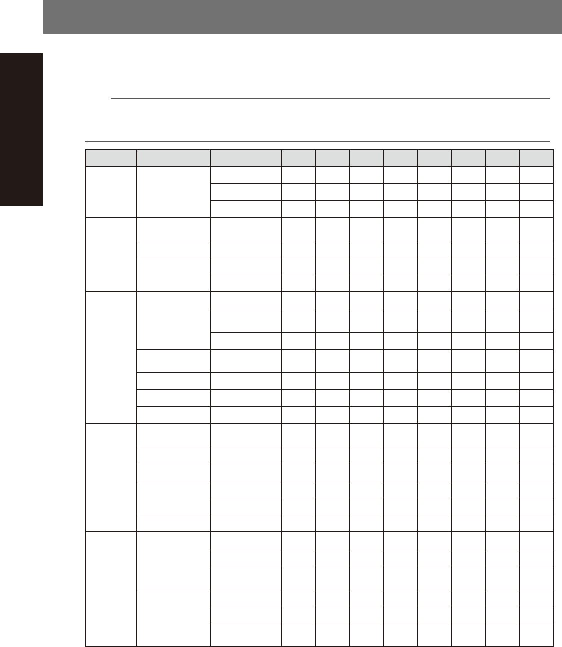
Maintenance list
The following maintenance procedure codes are used:
S: Inspection C: Cleaning L: Lubrication E: Replacement ( ): Procedure required only when a problem exists.
n
NOTE
Example) "C(E)" is indicated in the "3 Mon." field of [MU head] - [Switching Valve] - [Filter] in the list shown below. This
means that the filter needs to be cleaned at intervals of 3 months. If contaminants cannot be removed, replace the
filter with a new one.
Section Unit name Check items Daily Weekly Monthly 3 Mon. 6 Mon. 1 Year 2 Years 3 Years
All heads Nozzle
Air path S(C) C
Spring action SCL
Nozzle tip S(C) C
MU head
unit
Leaf spring
Nozzle mounting
status
S(E)
Switching valve Filter C(E)
Spline shaft
Inside (air path) C
Z-axis operation S
RS head
unit
Rotary unit
Nozzle shaft tip SCL
Upper part of
nozzle shaft
CL
Filter S(E)
Vacuum switching
mechanism
Spool CL
Vacuum line Packing E
R-axis/N-axis Scissors gear CL
Air line Blow valve E
FL head
unit
Leaf spring/
Roller lock
Nozzle mounting
status
S(E)
R-axis Scissors gear CL
Z-axis Ball screw CL
Spline shaft
Outside CL
Inside (air path) C
Switching valve Filter C(E)
X-Y axes
X-axis
Ball screw SCL
Guide SCL
Linear scale
(2-beam type only)
SC
Y-axis
Guide SCL
Linear scale SC
Y-axis cable
carrier chain link
E
iii
Introduction
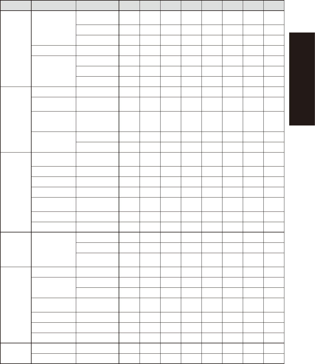
Section Unit name Check items Daily Weekly Monthly 3 Mon. 6 Mon. 1 Year 2 Years 3 Years
Conveyor
Board transport
unit
Board detection
sensor
SC
Conveyor belt S(E)
Guide • Pulley SC
PU-axis Ball screw CL
W-axis
Ball screw CL
Guide CL
Hexagon spline CL
Vision
system
Lighting
unit
Fiducial camera Mirror C
Multi-vision
camera
Protective glass/
Mirror
SC C
Side-view camera
(Supplied with multi-
vision camera)
Mirror C
RS head
Side-view camera
*1
Prism C
Light adjustment A
Base and
other units
Feeder float
sensor
Laser beam
emitter & receiver
SC
Tape cutter
*2
Tape cutter S S(L) E
Controller Filter C(E)
Air intake fan Filter C(E)
Air base MACS
(4-beam type only)
Lens C
Air/mist filter Filter C(E)
Vacuum pump Cup packing, etc. E
Feeder
exchange
carriage
Feeder exchange
carriage
Feeder plate SC
Cam follower CL
Guide rail cover
clamp
CL
cATS
Magazine/Pallet S
AZ-axis
Ball screw CL
Guide CL
AH-axis
Guide, ball guide,
rack & pinion
CL
Magazine shaft Ball guide CL
Pallet clamp Guide CL
Vertical guide Guide CL
Option
Ionizer Discharge needle C E
UPS Battery E
*1 Light adjustment of RS head side-view camera
The lighting illuminance of RS head side-view camera gradually decreases by long-term use. YAMAHA recommends to
adjust the light illuminance once every 2 years. The adjustment must be performed by YAMAHA service personnel.
Contact YAMAHA sales representatives for details.
*2
Maintaining tape cutter
YAMAHA recommends to inspect a tape cutter (and to lubricate with disassembly if needed) once a year, although this
may vary depending on the machine condition or machine operating environment. YAMAHA also recommends to replace
tape cutter blade once every 3 years. Tape cutter inspection, lubrication with disassembly, and replacing tape cutter
blade must be performed by YAMAHA service personnel as failure in these tasks cause serious injury. Contact YAMAHA
sales representatives for details.

Chapter 1 Maintenance
Contents
1. Maintaining machine performance 1-1
1.1 Essential conditions and working environment 1-1
1.2 Importance of periodic inspections and cleaning 1-2
2. Preparing for maintenance tasks 1-3
2.1 Consumable parts 1-3
2.1.1 MU head unit 1-3
2.1.2 RS head unit 1-5
2.1.3 FL head unit 1-8
2.1.4 Replaceable parts for all models 1-10
2.2 Replaceable parts 1-12
2.2.1 MU head unit 1-12
2.2.2 RS head unit 1-13
2.2.3 FL head unit 1-14
2.3 Maintenance tools 1-15
2.3.1 Cleaning tools 1-15
2.3.2 Lubricating tools and grease 1-17
2.3.3 Special tools 1-19
2.4 Required tools 1-20