YSM40R_Mainte_E.pdf - 第132页
3-62 3 Periodic maintenance items 7 Wipe the rest of the ball scre w and guides. e 1. Set the feeder exchange carriage and cancel emergency stop. 2. Narrow the conveyor width manually, press the emergency stop button aga…
3-61
3
Periodic maintenance items
5.3.3 Cleaning/lubricating W-axis ball screw and guides
This section describes the procedure for cleaning and lubricating the conveyor W-axis ball screw and guides.
See "Chapter 5 Lubricating points" for lubricating points and lubricating type.
1
Set the conveyor width of Lane 1 to
the maximum.
Press the [Unit]-[Conveyor]-[Width] button
and set the conveyor width of Line 1 to the
maximum.
2
Lower the push-up plates of Lane 1.
Make sure that the push-up plates are
lowered. If not lowered, press the [Unit]-
[Conveyor]-[Push Up] button to lower the
push-up plates (2 plates for stages 1 and 2)
of Lane 1.
3
Prepare for work.
e
1. Remove all items sensitive to magnetic
fields such as wristwatches and magnetic
ID cards.
2. Press the emergency stop button to put
the machine in emergency stop.
3. Use the CLAMP ON/OFF switch to lower
the feeder exchange carriage and
detach it.
4
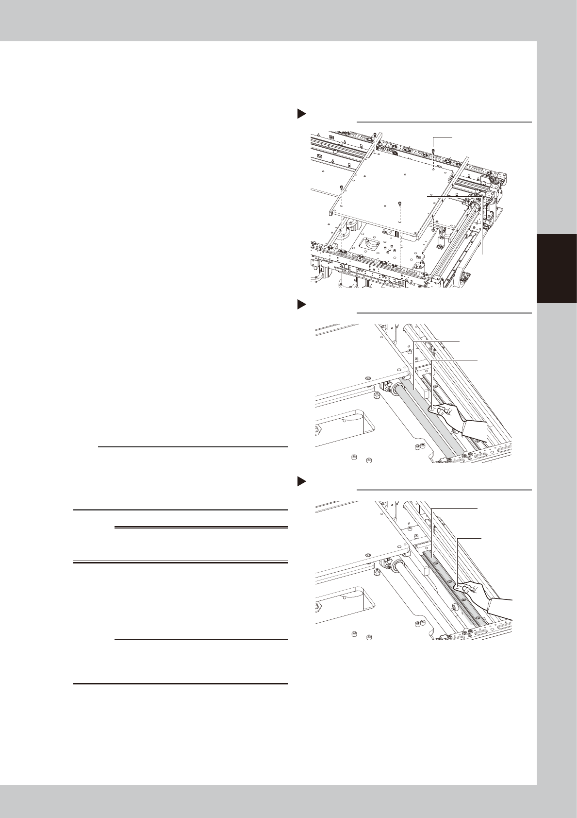
Detach the push-up plate.
Use a hex wrench (4) to remove the bolts (4
places per stage) that detach the push-up
plates, and then remove the push-up plates.
53378-N9-00
n
NOTE
If it is difficult to clean the ball screw and guide due to
the tape cutter duct, then remove the tape cutter
duct. Note, however, that emergency stop cannot be
canceled when the tape cutter duct is removed. So
you will have to reattach it to cancel emergency stop.
w
WARNING
THE PUSH-PLATE IS A HEAVY ITEM, AND IT MUST THEREFORE
BE HANDLED WITH CARE TO AVOID INJURY.
5
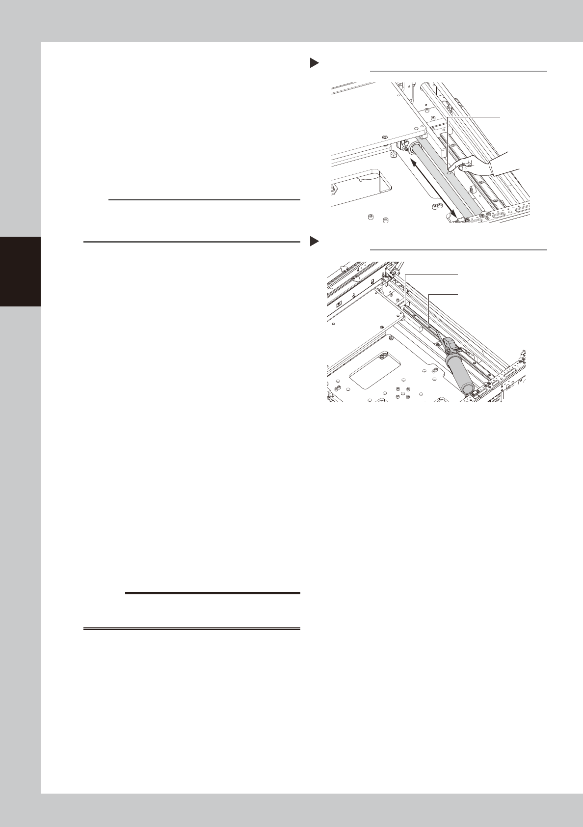
Clean the ball screw.
Wipe away old grease and dirt from the
entire ball screw with a lint-free cloth.
53379-N9-00
c
CAUTION
Carefully wipe the lead grooves of the ball screw during
cleaning. After cleaning, make sure that no dust, lint
and debris remain on the ball screw.
6
Clean the guide.
Wipe away old grease and dirt from the
entire guide with a lint-free cloth.
53380-N9-00
Removing the push-up plate
Step 4
Push-up plate securing
bolts (4 bolts)
Push-up plate
Cleaning the ball screw
Step 5
Cleaning cloth
Ball screw
Cleaning the guide
Step 6
Cleaning cloth
Guide
3-62
3
Periodic maintenance items
7
Wipe the rest of the ball screw and
guides.
e
1. Set the feeder exchange carriage and
cancel emergency stop.
2. Narrow the conveyor width manually,
press the emergency stop button again,
and remove the feeder exchange
carriage.
3. Wipe the rest of the ball screw and
guides that could not be wiped.
n
NOTE
If it is difficult to clean the ball screw and guide due to
the tape cutter duct, then detach the tape cutter
duct.
8
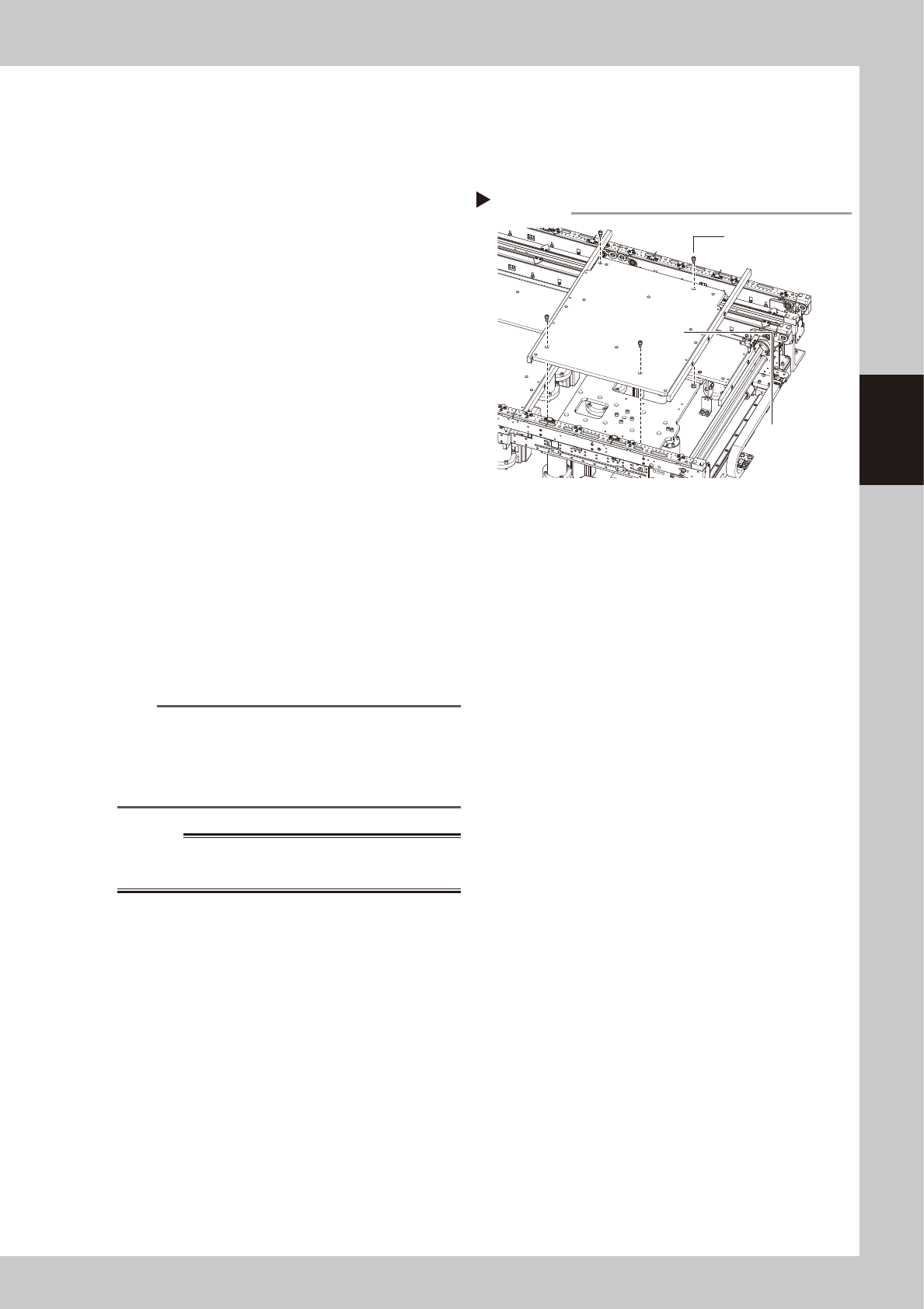
Apply grease to the ball screw.
Apply a uniform coat of the specified grease
(NSL) by hand over the surface and lead
grooves of the ball screw.
53381-N9-00
9
Apply grease to the guides.
Use a grease gun (30° bent nozzle type) to
inject the specified grease (NSL) into the
W-axis guide grease nipples.
53382-N9-00
0
Apply grease to the rest of the ball
screw.
e
1. Set the feeder exchange carriage and
cancel emergency stop.
2. Manually set the conveyor width to the
maximum, press the emergency stop
button, and detach the feeder
exchange carriage.
3. Apply grease to the rest of the ball screw
where you could not apply grease.
4. Wipe off grease if it is accumulated in
the guides.
q
Return push-up plates to original
positions..
w
WARNING
THE PUSH-UP PLATES ARE HEAVY. HANDLE CAREFULLY NOT
TO DROP THEM TO AVOID INJURY.
w
Clean and lubricate Lane 2.
Clean and lubricate the ball screw and
guides on Lane 2 using the same procedures
as for Lane 1.
Applying grease to the ball screw
Step 8
Apply a uniform
coating.
Grease
Applying grease to the guide
Step 9
Grease nipple
Grease gun (30° bent type)
3-63
3
Periodic maintenance items
5.3.4 Cleaning/lubricating PU-axis ball screw
This section describes the procedure for cleaning and lubricating the PU-axis ball screws. See "Chapter 5
Lubricating points" for lubricating points and lubricating type.
1
Set the conveyor width of Lane 1 to
the maximum.
Press the [Unit]-[Conveyor]-[Width] button
and set the conveyor width of Line 1 to the
maximum.
2
Lower the push-up plates of Lane 1.
Make sure that the push-up plates are
lowered. If not lowered, press the [Unit]-
[Conveyor]-[Push Up] button to lower the
push-up plates (2 plates for stages 1 and 2)
of Lane 1.
3
Prepare for work.
e
1. Remove all items sensitive to magnetic
fields such as wristwatches and magnetic
ID cards.
2. Press the emergency stop button to put
the machine in emergency stop.
3. Use the CLAMP ON/OFF switch to lower
the feeder exchange carriage and
detach it.
4
Remove the push-up plates.
Use a hex wrench (4) to remove the bolts (4
places per stage) that secure the push-up
plates, and then remove the push-up plates.
53378-N9-00
n
NOTE
If it is difficult to clean the ball screw due to the tape
cutter duct, detach the tape cutter duct. Note,
however, that emergency stop cannot be canceled
when the tape cutter duct is detached. So it is required
to reattach it to cancel emergency stop.
w
WARNING
THE PUSH-UP PLATES ARE HEAVY. HANDLE CAREFULLY NOT
TO DROP THEM TO AVOID INJURY.
5
Raise the PU-axis.
1. Set the feeder exchange carriage and
cancel emergency stop.
2. Press the [Unit]-[Conveyor]-[Push Up]
button and enter “0.1 mm” in the board
thickness dialog box to raise the push-up
plates (2 plates for stages 1 and 2) of
Lane 1.
e
3. Press the emergency stop button again
and detach the feeder exchange
carriage.
Removing the push-up plate
Step 4
Push-up plate securing
bolts (4 bolts)
Push-up plate