YSM40R_Mainte_E.pdf - 第34页
Chapter 1 Maintenance Contents 1. Maintaining machine per formance 1-1 1.1 Essential conditions and working environment 1-1 1.2 Importance of periodic inspections and cleaning 1-2 2. Preparing for maintenance tasks 1-3 2…
iii
Introduction
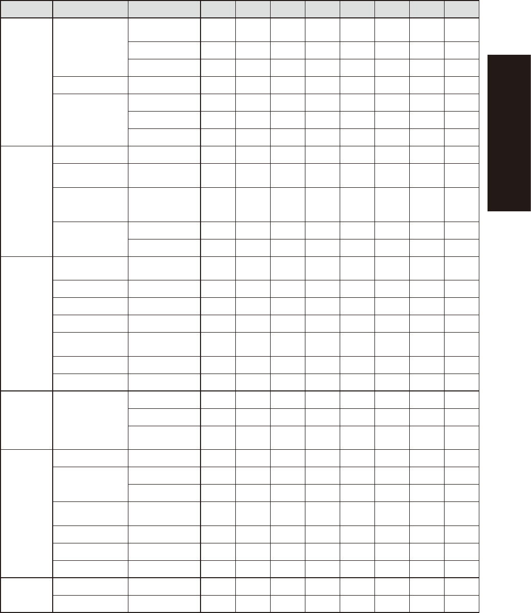
Section Unit name Check items Daily Weekly Monthly 3 Mon. 6 Mon. 1 Year 2 Years 3 Years
Conveyor
Board transport
unit
Board detection
sensor
SC
Conveyor belt S(E)
Guide • Pulley SC
PU-axis Ball screw CL
W-axis
Ball screw CL
Guide CL
Hexagon spline CL
Vision
system
Lighting
unit
Fiducial camera Mirror C
Multi-vision
camera
Protective glass/
Mirror
SC C
Side-view camera
(Supplied with multi-
vision camera)
Mirror C
RS head
Side-view camera
*1
Prism C
Light adjustment A
Base and
other units
Feeder float
sensor
Laser beam
emitter & receiver
SC
Tape cutter
*2
Tape cutter S S(L) E
Controller Filter C(E)
Air intake fan Filter C(E)
Air base MACS
(4-beam type only)
Lens C
Air/mist filter Filter C(E)
Vacuum pump Cup packing, etc. E
Feeder
exchange
carriage
Feeder exchange
carriage
Feeder plate SC
Cam follower CL
Guide rail cover
clamp
CL
cATS
Magazine/Pallet S
AZ-axis
Ball screw CL
Guide CL
AH-axis
Guide, ball guide,
rack & pinion
CL
Magazine shaft Ball guide CL
Pallet clamp Guide CL
Vertical guide Guide CL
Option
Ionizer Discharge needle C E
UPS Battery E
*1 Light adjustment of RS head side-view camera
The lighting illuminance of RS head side-view camera gradually decreases by long-term use. YAMAHA recommends to
adjust the light illuminance once every 2 years. The adjustment must be performed by YAMAHA service personnel.
Contact YAMAHA sales representatives for details.
*2
Maintaining tape cutter
YAMAHA recommends to inspect a tape cutter (and to lubricate with disassembly if needed) once a year, although this
may vary depending on the machine condition or machine operating environment. YAMAHA also recommends to replace
tape cutter blade once every 3 years. Tape cutter inspection, lubrication with disassembly, and replacing tape cutter
blade must be performed by YAMAHA service personnel as failure in these tasks cause serious injury. Contact YAMAHA
sales representatives for details.

Chapter 1 Maintenance
Contents
1. Maintaining machine performance 1-1
1.1 Essential conditions and working environment 1-1
1.2 Importance of periodic inspections and cleaning 1-2
2. Preparing for maintenance tasks 1-3
2.1 Consumable parts 1-3
2.1.1 MU head unit 1-3
2.1.2 RS head unit 1-5
2.1.3 FL head unit 1-8
2.1.4 Replaceable parts for all models 1-10
2.2 Replaceable parts 1-12
2.2.1 MU head unit 1-12
2.2.2 RS head unit 1-13
2.2.3 FL head unit 1-14
2.3 Maintenance tools 1-15
2.3.1 Cleaning tools 1-15
2.3.2 Lubricating tools and grease 1-17
2.3.3 Special tools 1-19
2.4 Required tools 1-20
1-1
1
Maintenance
1. Maintaining machine performance
The most important condition essential for maintaining the performance of the machine you purchased is
using it under good environmental conditions. Performing daily maintenance and periodic inspections is also
absolutely essential.
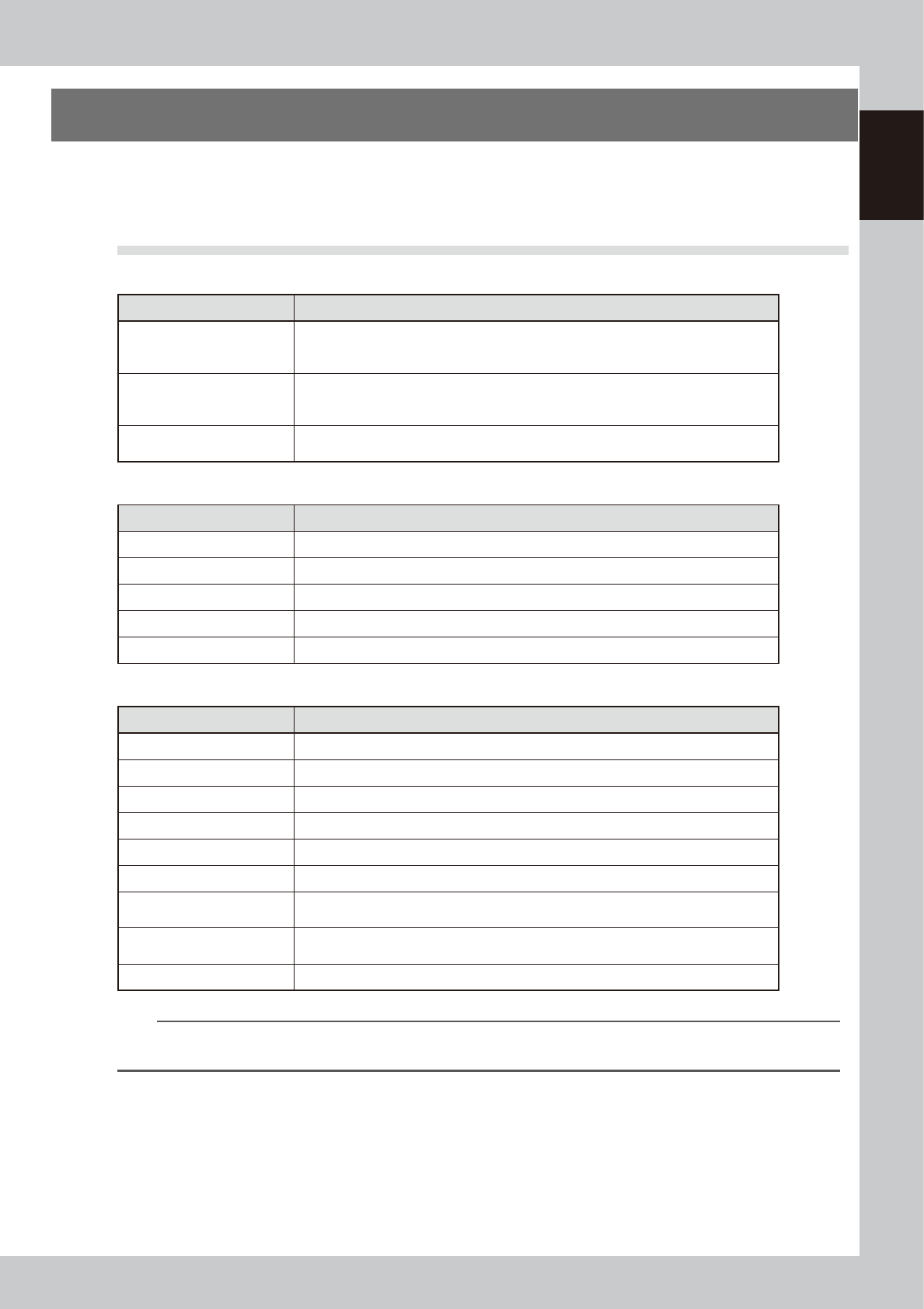
1.1 Essential conditions and working environment
n
Air
Item Description
Air pressure
Supply air pressure: 0.45MPa or more
Setting air pressure: 0.40MPa (0.39MPa to 0.41MPa)
Head unit air pressure: 0.040MPa (0.039MPa to 0.041MPa)
Air consumption
RS head (4-beam type) : 50Nl/min (average), 180Nl/min (max.)
MU head (2-beam and 4-beam types) : 30Nl/min (average), 140Nl/min (max.)
FL head (2-beam) : 30Nl/min (average), 140Nl/min (max.)
Use conditions
Air hose with inner diameter of 8mm or more should be used.
Clean air passed through air dryer and air filter should be used.
n
Power
Item Description
Power supply 200/208/220/240/380/400/416VAC (±10%), 3-phase AC line
Frequency 50Hz or 60Hz
Power supply capacity 13.9KVA
Average power consumption 3.2KW
Power supply connection Power cable conductor cross-section area: 10mm
2
minimum
n
Environment
Item Description
Noise Complies with EN61000-6-2 standard.
Humidity 20 to 80% (no condensation), optimal range: 50 to 60%
Temperature Functions guaranteed within 15 to 35°C. Machine precision guaranteed within 20 to 28°C.
Overvoltage category category III
Pollution degree degree 2
Altitude 1000 m or less above sea level
Installation
Flat level location sturdy enough so no vibration occurs during operation.
Wooden floors in particular are unsuitable.
Required floor flatness
When using feeder exchange carriages on the front and rear of the machine, the flatness
of the floor must be within 10 mm, including the area directly under the machine..
Floor load-bearing strength 1000kg/m
2
or more
n
NOTE
When using an industrial humidifier as static electricity prevention measures, be sure to use water equivalent to the DI
water.