YSM40R_Mainte_E.pdf - 第201页
A-1 Appendix 1. Specifications 1.1 Air regulator unit T he air regulator for controlling the air pressure to the machine's pneumatic units is located at the lower left panel on the rear side of the machine. Specify …

Appendix
Appendix
Contents
1. Specifications A-1
1.1 Air regulator unit A-1
1.2 Power connection terminals A-2
1.3 Connection between machines A-3
1.3.1 PREVIOUS INTERFACE connector A-3
1.3.2 NEXT INTERFACE connector A-4
2. Maintenance parts A-5
2.1 YSM40R main unit maintenance parts list A-5
2.2 Tray component supply unit maintenance parts list A-14
A-1
Appendix
1. Specifications
1.1 Air regulator unit
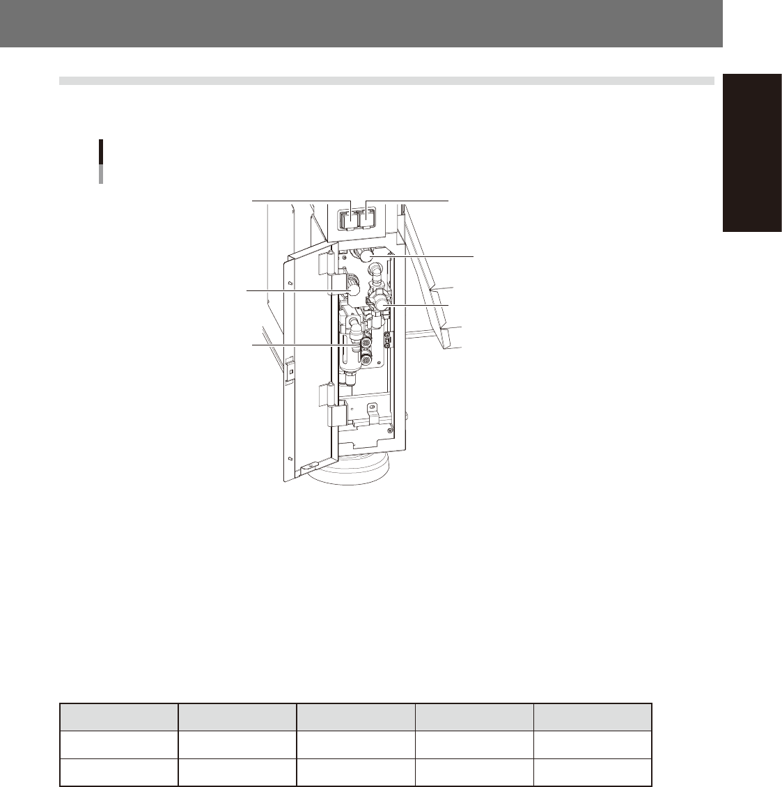
The air regulator for controlling the air pressure to the machine's pneumatic units is located at the lower left
panel on the rear side of the machine. Specify the appropriate air pressure setting shown below.
Air pressure regulator and pressure gauge
Setting air pressure gauge
[PNEUMATIC]
Setting air pressure regulator
[PNEUMATIC]
Air supply/exhaust switch
Head air pressure gauge
[HEAD BLOW]
Head air pressure regulator
[HEAD BLOW]
Source air connector
53A01-N9-00
n
Supply air pressure
This is the pressure of the source air supplied to the machine. Before setting the air pressure with the air regulator, make
sure that this supply air pressure is in the following optimal range.
YSM40R : 0.45MPa to 0.70MPa
n
Air pressure gauge (display)
When within the normal range, the air pressure displays in green. When the air pressure is beyond the upper/lower limit
values (air down detection), an error occurs, and the air pressure displays in red.
n
Air pressure setting values and upper/lower limit values
Head Setting Value Lower Limit Value Upper Limit Value
Setting air pressure Common 0.40Mpa (±0.01) 0.39Mpa 0.41Mpa
Head air pressure Common 0.040Mpa (±0.001) 0.039Mpa 0.041Mpa
n
Air supply/shutoff switch (valve)
Turning this switch to the right shuts off air supply and exhausts air that remains inside the machine.
n
Source air connector
Prepare an air hose with an inner diameter of at least 8 mm having a 40SH socket (Nitto Koki, or equivalent), and
connect it to this connector. Use dry, clean air passed through an air filter.
A-2
Appendix
1.2 Power connection terminals
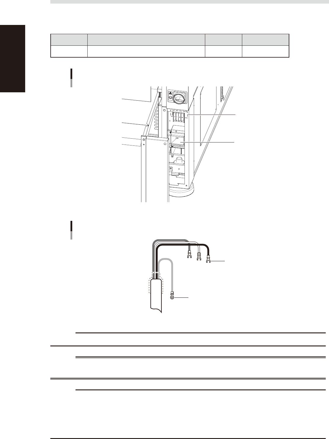
The power connection terminals are located inside the lower right panel on the front of the machine. Connect
the power cable leads as shown below to the L1, L2, L3 and ground terminal (PE) on the power terminal block.
n
Power supply specifications
Model name Power Frequency Power capacity
YSM40R 3-phase AC 200/208/220/240/380/400/416V (±10%) 50/60Hz 13.9kVA
Power input terminals
(L1, L2, L3) and ground terminal
Main breaker
Power connection terminals
53A02-N9-00
Ring-tongue crimp terminal
Insulated crimp terminal
Power cable
L2
L1
L3
PE
53A03-N9-00
c
CAUTION
Use a power cable whose conductor cross-section area is greater than 10 mm
2
.
w
WARNING
TO AVOID THE RISK OF ELECTRICAL SHOCK, MAKE SURE THAT THE POWER SOURCE IS OFF BEFORE CONNECTING THE
POWER CABLE. ALSO MAKE SURE THAT THE GROUND CABLE IS SECURELY CONNECTED TO THE MACHINE.
c
CAUTION
By referring to the figure above, be sure to connect the power cable correctly to the L1, L2 and L3 terminals on the
power input terminal block so that they are in the normal phase. Incorrect connection may cause the vacuum pump
to turn in the wrong direction and drastically shorten the service life of the components in the vacuum pump.
Before turning on the machine power, check with a phase rotation indicator. Alternatively, turn on the machine power
and bring a piece of paper near the front panel of the vacuum pump. If the paper is attracted to the pump, it is normal
(normal rotation).