YSM40R_Mainte_E.pdf - 第60页
2-5 2 Daily maintenance items 3 Select the item to be ex ecuted. After checking the displayed message, select the desired button. 54201-N9-00 n When selected [Y es] P erforms auto nozzle change and checks all relev ant n…
2-4
2
Daily maintenance items
1. Checking the nozzle
Solder sticking to the nozzle tip or a clogged nozzle hole can cause component pickup error and recognition
error. Inspect each nozzle periodically to prevent the errors.
1.1 Checking with software
n
How to check for a dirty nozzle (with the [Tip Dirt Check] button)
The term "dirty nozzle" as used here indicates shiny material such as solder adhering to the nozzle tip. This
shiny portion might be mistaken for a component and cause recognition errors. [Tip Dirt Check] is a tool that
judges the nozzle contamination status by recognizing the nozzle tip in the non-component status with the
camera. Regarding RS head, this function is available with machine equipped with multi-camera.
n
NOTE
The [Tip Dirt Check] is a function that recognizes the reflection of the light around the nozzle center. Therefore,
applicable nozzles are those with a small tip, such as Type 501A and 502A.
n
NOTE
As the nozzle type may vary depending on the machine, some machines may require additional settings. Contact
YAMAHA sales representatives for details.
1
(Without nozzle station) Replace
the nozzle.
1. Press the [Required Nozzles] button on
the "Setup" screen to check the nozzles
to be used for production.
e
2. Press the emergency stop button and
then open the machine safety cover.
3. Attach nozzles to be used for production
to head.
4. Close the machine safety cover and
then cancel the emergency stop.
n
NOTE
Step 1 can be skipped if the machine is equipped with
the nozzle station.
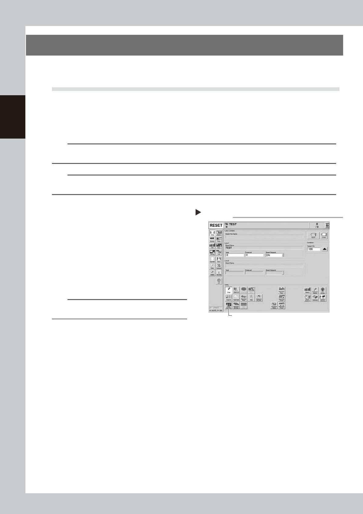
2
Press the [Tip Dirt Check] button
on the "Setup" screen.
54200-N9-00
Pressing the [Tip Dirt Check] button
Step 2
[Tip Dirt Check] button
2-5
2
Daily maintenance items
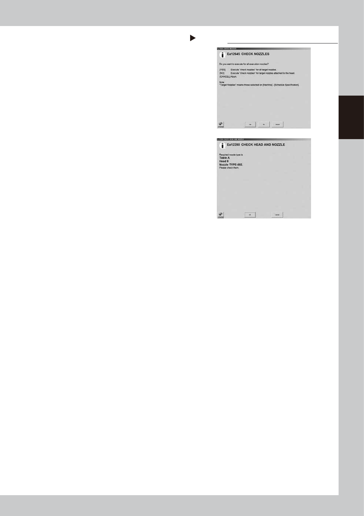
3
Select the item to be executed.
After checking the displayed message,
select the desired button.
54201-N9-00
n
When selected [Yes]
Performs auto nozzle change and checks all relevant
nozzles.
n
When selected [No]
Checks relevant nozzles of all nozzles currently
attached to the head.
4
Check the message.
Check the message. If the result is Not OK,
clean the nozzle referring to "1.2 Nozzle
cleaning" in Chapter 3.
Selecting item to be executed
Step 3
When selected [No]
2-6
2
Daily maintenance items
n
How to check for clogged nozzles (on the [Unit]-[Head] tab screen)
The term "clogged nozzle" used here indicates that material such as solder is adhering to the nozzle hole, causing a rise
in negative pressure even if no component is being picked up by the nozzle. This state might cause problems such as
component mounting errors. Check for clogged nozzles with the following procedures.
As the procedures of MU head, FL head and RS head differ, each procedure is described separately.
n
MU head and FL head
The following is the description of MU head with Type 502A nozzle as an example.
n
NOTE
When checking other nozzles and their vacuum levels, see "1.1.1 Vacuum level when nozzle is open" in this chapter.
e
1
Attach the nozzle.
Press the emergency stop button and attach
Type 502A nozzles to heads on selected
table to be checked. When the machine
has a nozzle station, press the [Nozzle
Change] button to change the nozzles.
54202-N9-00
2
Reset the numerical figure.
1. Open the [Unit] - [Head] tab screen.
Press the [Table selection] button and
select the table that has the head to be
checked.
2. Press the [Reset] button on the lower
right of the screen to reset the vacuum
level values.
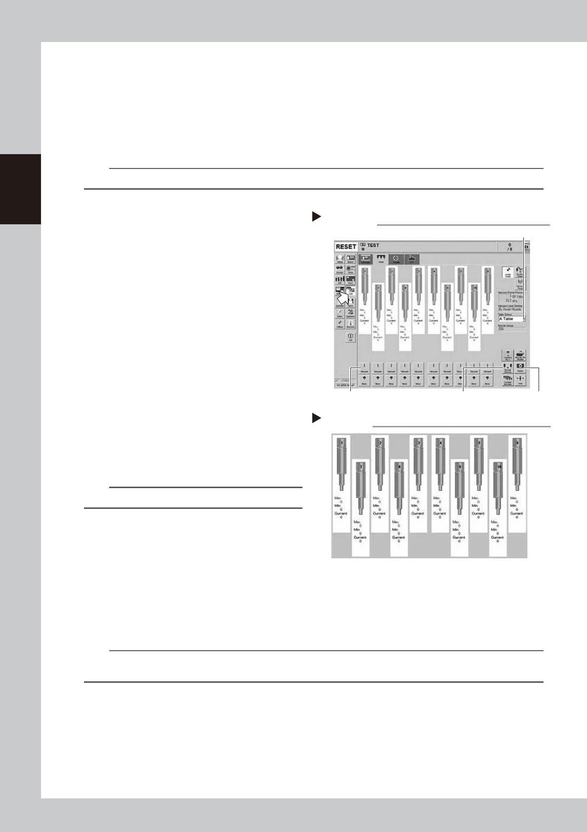
3
Generate negative pressure.
Press the [Vacuum] buttons on the [Unit]
- [Head] tab screen for the head to be
checked. When the value starts rising, wait 5
to 10 seconds and set to OFF. Perform this
task to all tables.
n
NOTE
The figure at right shows an example of the MU head.
4
Check the vacuum levels.
1. Check all "Max" values shown in red on
the [Head] tab. If the value is 75 or less, it
is in normal range.
2. If the value is higher than 75, the nozzle
hole might be dirty. See "1.2 Nozzle
cleaning" in Chapter 3 to clean the
nozzle.
54203-N9-00
n
NOTE
If a correct value cannot be obtained from steps 1 to 4 even after cleaning nozzle, the interior of the spline shaft
might be dirty.
Negative pressure generation
Step 1 to 3
[Nozzle Change] button[Vacuum] button [Reset] button
Table Select button
Negative pressure check
Step 4