00197001-04_UM_Smart_Pin_Support_X-Series-S_SX12V2_DE_EN.pdf - 第107页
5 Sample Applications 5.1 Support pin placement User Manual / Bedienungsanleitung SIPLACE X-Series S, SX1/SX2 V2 Smart Pin Support Operation and Configura- tion 05/2019 107 Fig.48: Remove support pin manually (sample SX…
5 Sample Applications
5.1 Support pin placement
106 User Manual / Bedienungsanleitung SIPLACE X-Series S, SX1/SX2 V2 Smart Pin Support Operation and Configura-
tion 05/2019
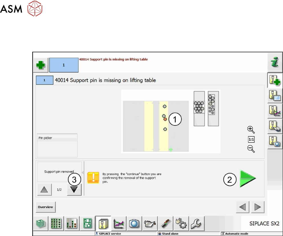
5.1.2 Support Pin Is Missing on the Lifting Table
If a support pin is missing at the expected position on the lifting table, the following dialog box is
displayed on the GUI of the station software.
Fig.47: Support pin is missing on the lifting table (sample SX2)
The missing support pin is displayed in red (1).
► Click on the Continue button to confirm that the support pin has been removed (2).
or
► Click on the arrow (3) to open the following dialog box:
5 Sample Applications
5.1 Support pin placement
User Manual / Bedienungsanleitung SIPLACE X-Series S, SX1/SX2 V2 Smart Pin Support Operation and Configura-
tion 05/2019
107
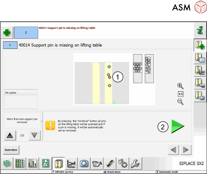
Fig.48: Remove support pin manually (sample SX2)
► Click on the Continue button (2).
This confirms that all support pin positions are scanned and if support pins cannot be found they
will be set to automatically removed without any further confirmation requests.
5 Sample Applications
5.2 Smart Pin Support and Long Board Option - (LBO)
108 User Manual / Bedienungsanleitung SIPLACE X-Series S, SX1/SX2 V2 Smart Pin Support Operation and Configura-
tion 05/2019
5.2 Smart Pin Support and Long Board Option - (LBO)
The following example displays how to combine Smart Pin Support and the Long Board Option
(LBO) with each other.
Requirements:
●
A setup in which stations with configured LBO support are present.
●
A support pin list with support pins is assigned to the board.
●
The Long Board Option must be enabled in the Line Editor. After that, the offset for the LBO
stopper may be corrected in the Setup Editor under the Long Board tab.
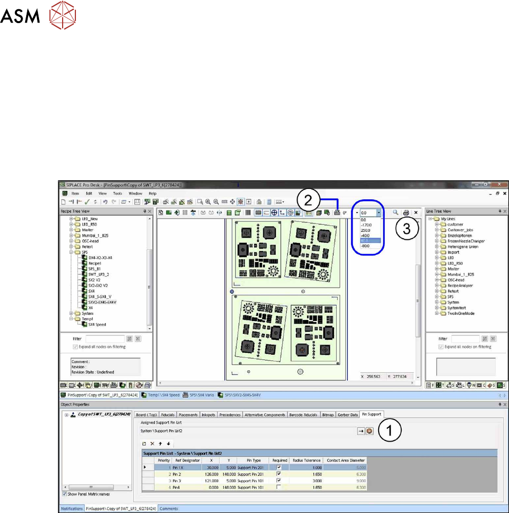
Fig.49: Board Editor: LBO setup
► Open the Board Editor and select the Pin Support tab(1).
► Click on the Setup icon(2).
The stopper positions that have been defined in the setup will be displayed in a drop down list(3).
► Select the desired stopper positions in relation to the board from the drop down list.
The support pins will be adjusted accordingly.
► Make sure that the support pins at the different support pin positions do not collide with the
components.
If the board is moved into the machine with a different than 0°, another angle value may be set in
the tool bar and the offset checked with other angle values.