00197001-04_UM_Smart_Pin_Support_X-Series-S_SX12V2_DE_EN.pdf - 第85页
3 Configuring Smart Pin Support in SIPLACE Pro 3.2 Defining Support Pin Positions in the Board Editor User Manual / Bedienungsanleitung SIPLACE X-Series S, SX1/SX2 V2 Smart Pin Support Operation and Configura- tion 05/20…
3 Configuring Smart Pin Support in SIPLACE Pro
3.2 Defining Support Pin Positions in the Board Editor
84 User Manual / Bedienungsanleitung SIPLACE X-Series S, SX1/SX2 V2 Smart Pin Support Operation and Configura-
tion 05/2019
3.2.2.5 Automatical Collision Check
Potential pin collisions with components, conveyor rails or other support pins can be checked in the
Pin Support tab of the Board Editor.
The following values / parts are used for the collision checks:
●
for components:
Support pin tolerance
●
for long board:
Stopper offsets (adjustable in the tool bar)
●
for conveyor rails:
Support pin base
Processing orientation (adjustable in the tool bar)
●
for other support pins:
Base
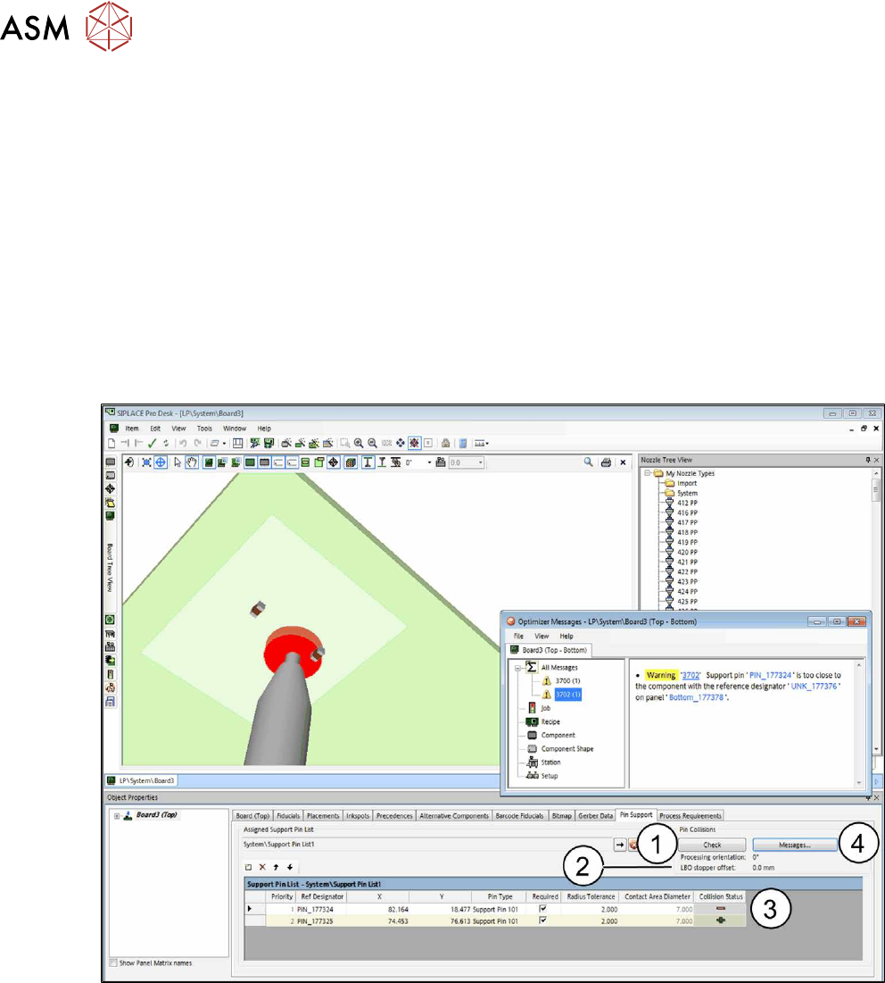
Fig.26: Automatical collision check
► Click on the Check button (1).
The parameters used for the simulated processing orientation and for the stopper offset (2) are dis-
played (adjustable in the tool bar).
After the check, a collision status (3) is displayed for each support pin:
(+) if no collision was detected
(-) if at least one collision exists. A detailed description is displayed in the message window.
► Click on the Messages … button (4) to display explanatory information to all collision events.
The collision check checks the selected board and all boards with the checkmark "Use" in the dia-
log (see 3.2.4 "Linking Multiple Boards To Each Other" [}89]).
Changes are not valid until the board has been closed and reopened.
3 Configuring Smart Pin Support in SIPLACE Pro
3.2 Defining Support Pin Positions in the Board Editor
User Manual / Bedienungsanleitung SIPLACE X-Series S, SX1/SX2 V2 Smart Pin Support Operation and Configura-
tion 05/2019
85
Visual Collision Check
The collision events are displayed in red in the graphic.
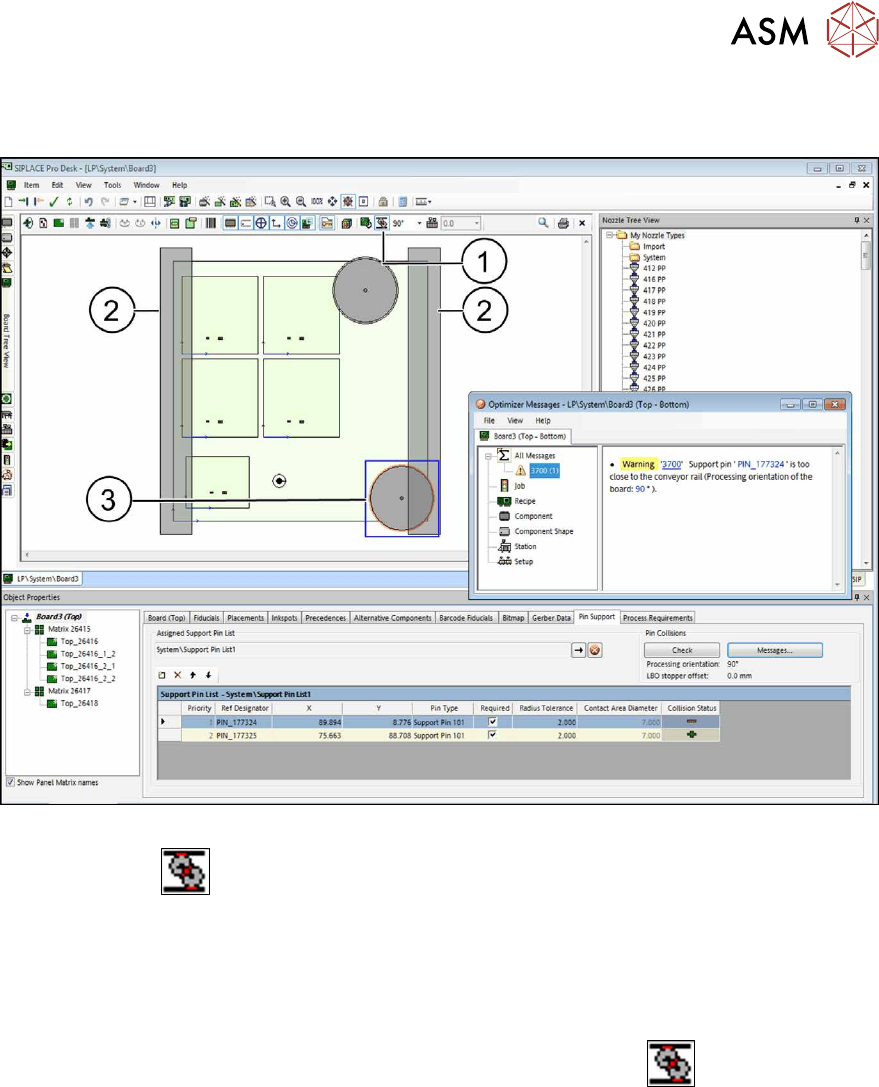
Fig.27: Support pin: Visual collision check – it should NOT look like that
By clicking on the
button (1), the conveyor rails(2), the pin bases and the components are
displayed. In the figure above it is visible that a pin base(3) collides with a conveyor rail to the
right.
► Move the support pins so that the pin bases do not collide with other pin bases, components
or conveyor rails.
If necessary, you may change the processing orientation of the board for the collision check.
► Select the desired rotation from the drop down list to the right of the
button (1).
Thereafter, the board and the conveyor rails (2) are displayed in the selected direction.
3 Configuring Smart Pin Support in SIPLACE Pro
3.2 Defining Support Pin Positions in the Board Editor
86 User Manual / Bedienungsanleitung SIPLACE X-Series S, SX1/SX2 V2 Smart Pin Support Operation and Configura-
tion 05/2019
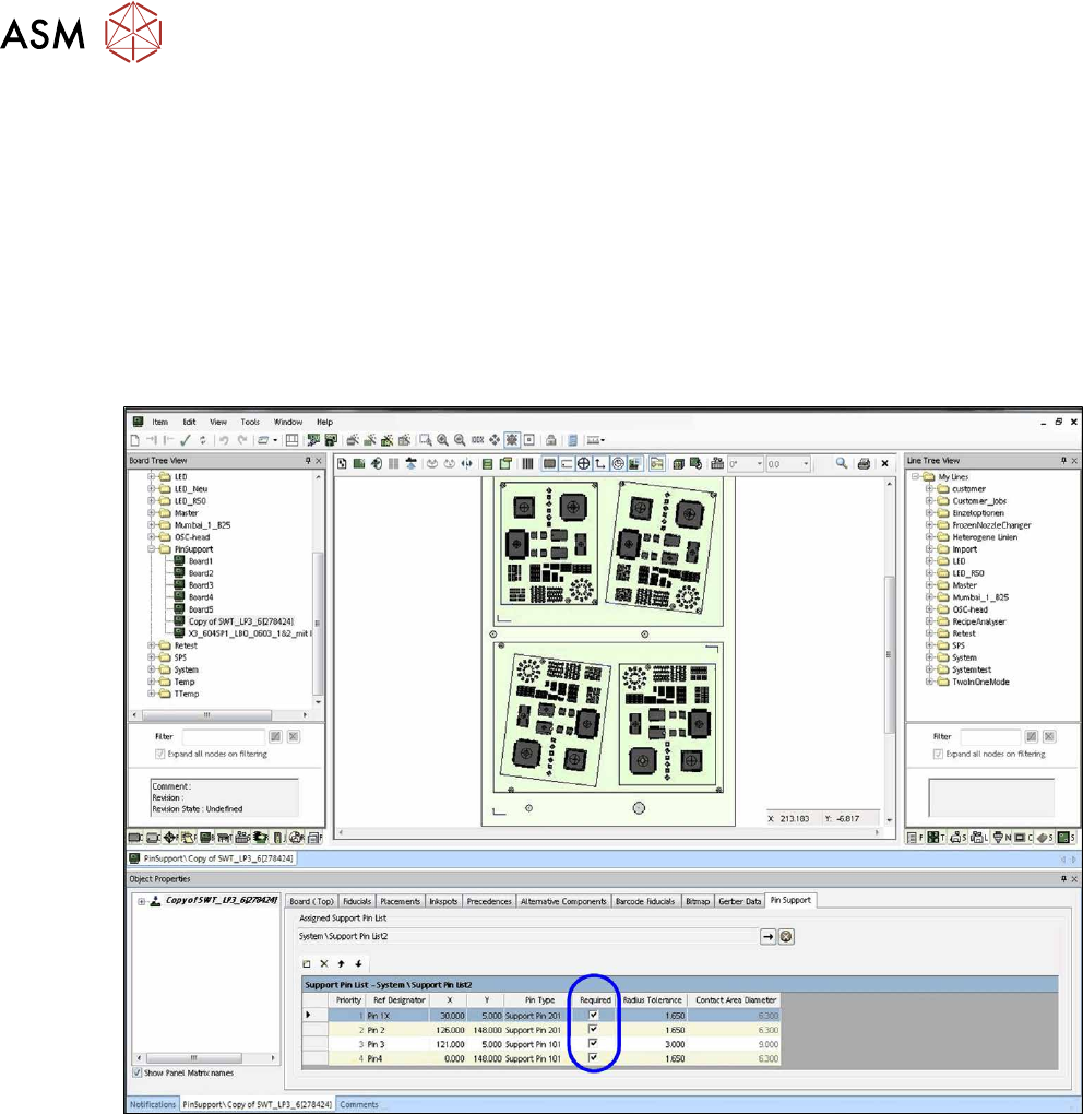
3.2.2.6 Defining Production Parameters
You can define whether a support pin position is required or not. When a new support pin position
is created, the Required property is activated by default. If a support pin cannot be placed at this
support pin position at the station, production is stopped with an error message. If Required is
deactivated for a support pin position (i.e. the support pin position is optional), the machine will try
to place a support pin at this support pin position. If this is not possible, an error message will not
be displayed at the station and the machine will try to place a support pin at the next support pin
position. The support pins that are not required will be displayed in blue in the graphic.
The order of the support pins to be placed is displayed in the Priority column. All required support
pins will be placed first, followed by all optional support pins in the order shown. In dual conveyor
mode this priority is considered for both lanes.
Fig.28: Defining production parameters