00197001-04_UM_Smart_Pin_Support_X-Series-S_SX12V2_DE_EN.pdf - 第90页
3 Configuring Smart Pin Support in SIPLACE Pro 3.3 Checking Production Parameters in the Recipe Editor 90 User Manual / Bedienungsanleitung SIPLACE X-Series S, SX1/SX2 V2 Smart Pin Support Operation and Configura- tion 0…
3 Configuring Smart Pin Support in SIPLACE Pro
3.2 Defining Support Pin Positions in the Board Editor
User Manual / Bedienungsanleitung SIPLACE X-Series S, SX1/SX2 V2 Smart Pin Support Operation and Configura-
tion 05/2019
89
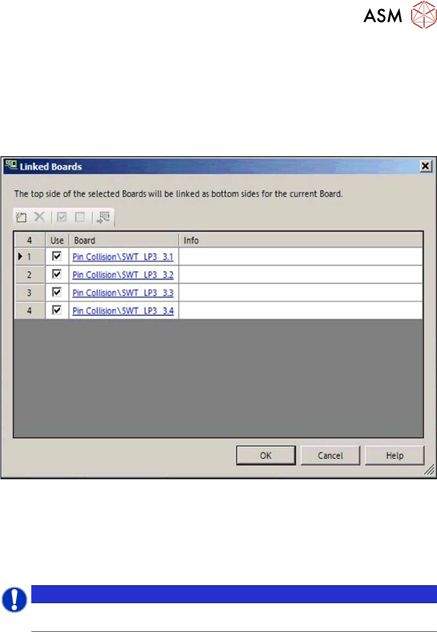
3.2.4 Linking Multiple Boards To Each Other
If different boards are used to define top side and underside of the board, these boards may now
be linked to each other for the collision check of the support pins, provided that no board underside
is defined for the currently selected board. Only the own underside or the top side of other boards
may be set as link for the board bottom side.
► Click on the Link Board Side Data button in the Board Editor.
The following dialog opens in which one or multiple boards may be selected or added to be dis-
played as board underside.
Fig.31: Linking boards to each other
The board top side of the selected board will be displayed as board underside of the current board
in the 3D view.
The board top side of the linked board will be displayed as board underside in the 2D view by click-
ing on the "Show underside" icon.
Single, linked boards can be hidden in the graphical view. For this, the checkmark has to be re-
moved from the Use field in the dialog box.
NOTICE
Art und Quelle der Gefahr
It is not possible to switch to the board underside if linked boards are selected.
3 Configuring Smart Pin Support in SIPLACE Pro
3.3 Checking Production Parameters in the Recipe Editor
90 User Manual / Bedienungsanleitung SIPLACE X-Series S, SX1/SX2 V2 Smart Pin Support Operation and Configura-
tion 05/2019
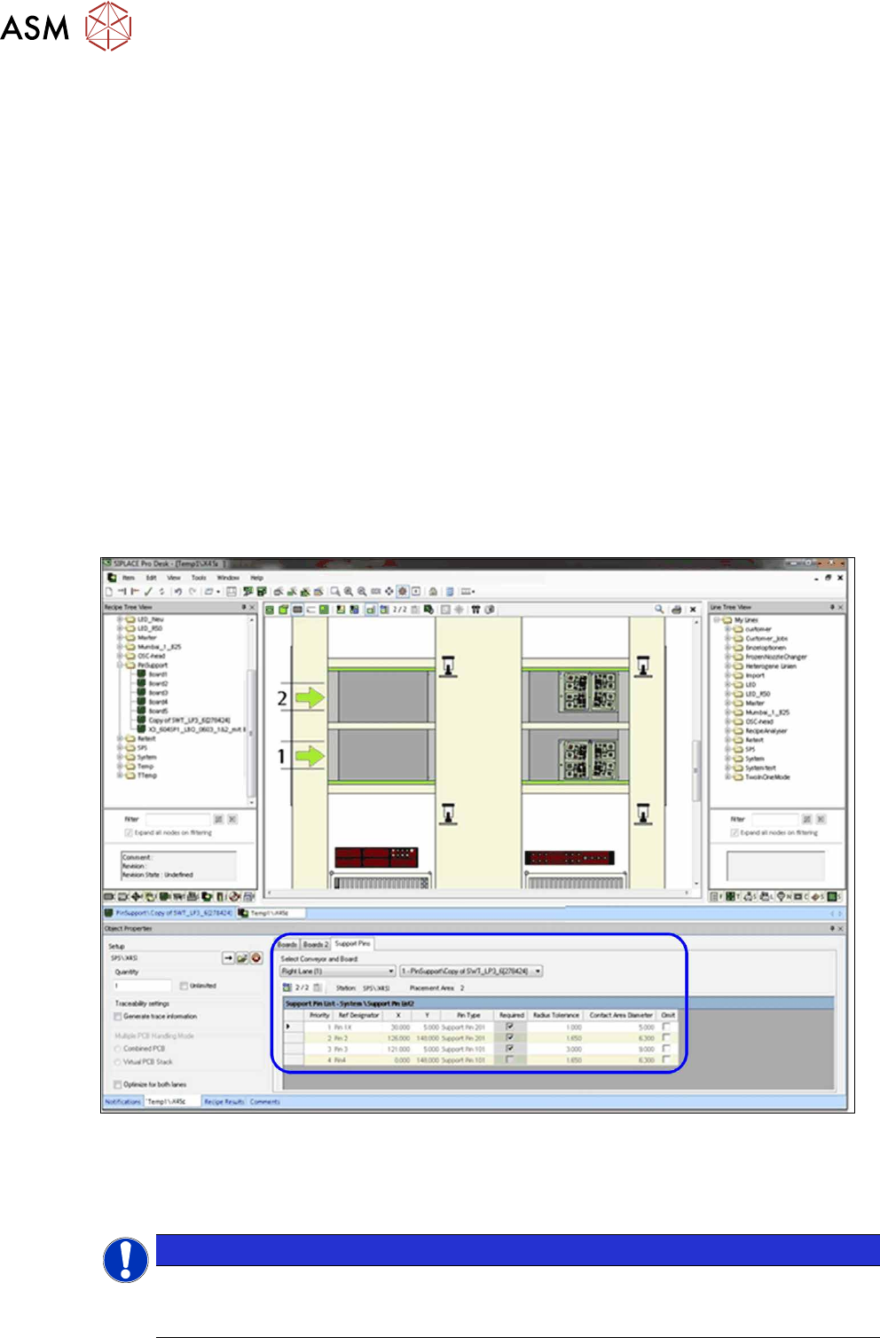
3.3 Checking Production Parameters in the Recipe Editor
The production parameters for the defined support pin positions can be checked in the Recipe Ed-
itor. Additionally, you can set the Omit property for each support pin position per placement area.
For this, the board has to be moved through the different placement areas. The support pin posi-
tions are saved for each processing area for the stations in the selected line.
If you don't make any changes in the Recipe Editor, the support pin positions that are defined in the
Board Editor are active for the board and are sent to the stations on which Smart Pin Support is in-
stalled and activated.
Meaning of the Markings
●
Required is ticked:
the support pin position has to be provided with a support pin before placement starts.
●
Omit is ticked:
the support pin position is omitted.
3.3.1 Setting Production Parameters
Prerequisites
●
SIPLACE Pro Desk is started.
●
A recipe is opened in the Recipe Editor.
●
The recipe contains a setup and a board with defined support pin positions.
Fig.32: Recipe Editor – Board with support pin positions (sample X4iS)
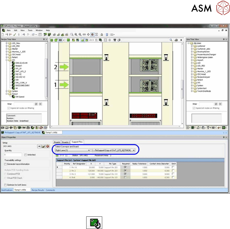
► Switch to the Support Pins tab.
► Select the conveyor (already preset in single conveyor mode).
► Select a board with already defined support pin positions.
NOTICE
Support pin data is not displayed.
If the support pin data is not displayed during the first edit, click on the Create button to cre-
ate the support pin data.
3 Configuring Smart Pin Support in SIPLACE Pro
3.3 Checking Production Parameters in the Recipe Editor
User Manual / Bedienungsanleitung SIPLACE X-Series S, SX1/SX2 V2 Smart Pin Support Operation and Configura-
tion 05/2019
91
Fig.33: Recipe Editor – Selecting conveyor and board (sample X4iS)
The defined support pin positions are saved for each processing area. The settings for the currently
selected placement area are listed. In the graphic view you can switch back and forth between the
board top side and underside via the
button in order to verify both sides.