00197001-04_UM_Smart_Pin_Support_X-Series-S_SX12V2_DE_EN.pdf - 第92页
3 Configuring Smart Pin Support in SIPLACE Pro 3.3 Checking Production Parameters in the Recipe Editor 92 User Manual / Bedienungsanleitung SIPLACE X-Series S, SX1/SX2 V2 Smart Pin Support Operation and Configura- tion 0…
3 Configuring Smart Pin Support in SIPLACE Pro
3.3 Checking Production Parameters in the Recipe Editor
User Manual / Bedienungsanleitung SIPLACE X-Series S, SX1/SX2 V2 Smart Pin Support Operation and Configura-
tion 05/2019
91
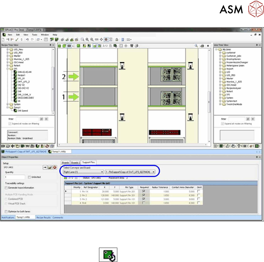
Fig.33: Recipe Editor – Selecting conveyor and board (sample X4iS)
The defined support pin positions are saved for each processing area. The settings for the currently
selected placement area are listed. In the graphic view you can switch back and forth between the
board top side and underside via the
button in order to verify both sides.
3 Configuring Smart Pin Support in SIPLACE Pro
3.3 Checking Production Parameters in the Recipe Editor
92 User Manual / Bedienungsanleitung SIPLACE X-Series S, SX1/SX2 V2 Smart Pin Support Operation and Configura-
tion 05/2019
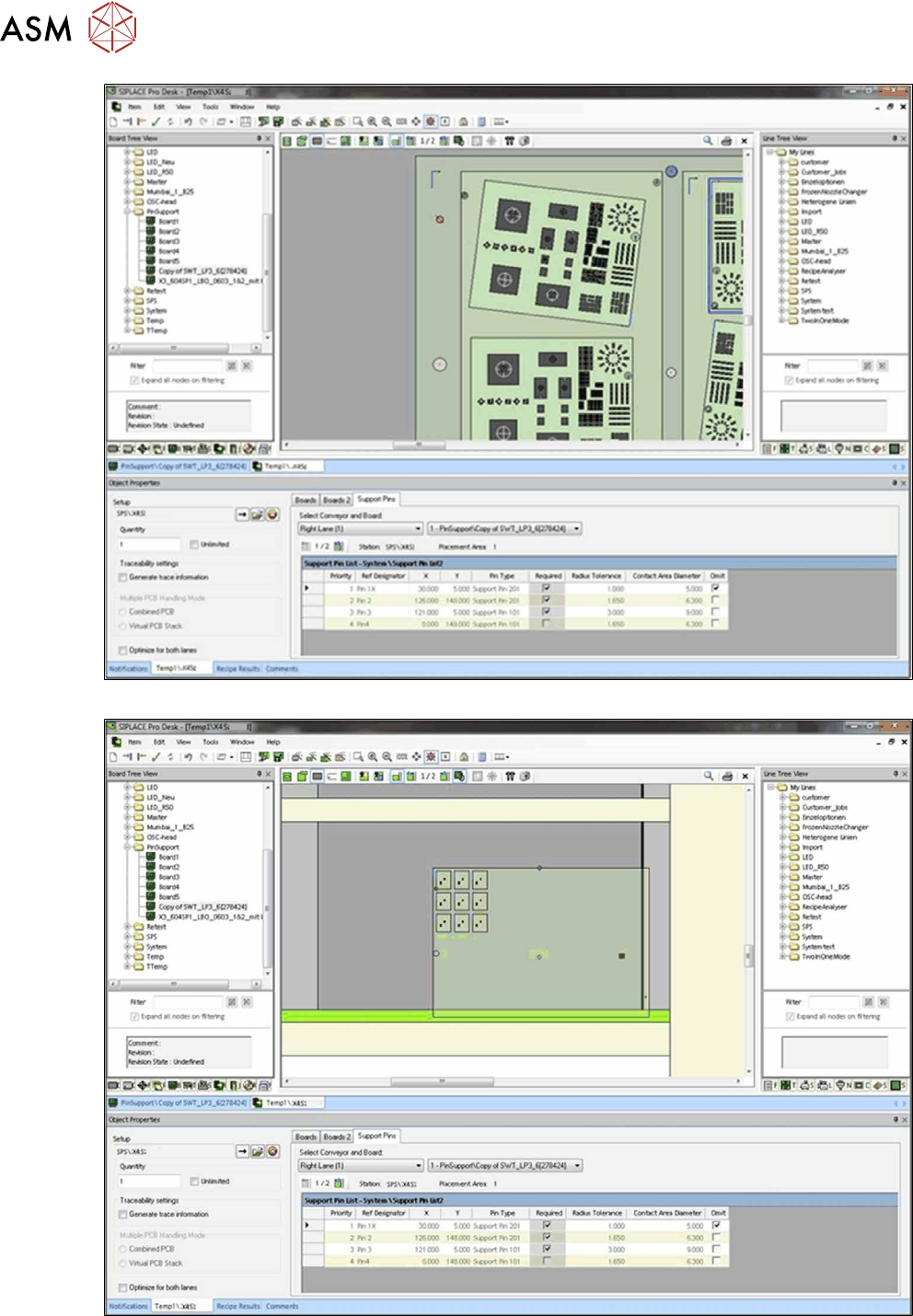
Fig.34: Recipe Editor – Board top side
Fig.35: Recipe Editor – Board underside
3 Configuring Smart Pin Support in SIPLACE Pro
3.3 Checking Production Parameters in the Recipe Editor
User Manual / Bedienungsanleitung SIPLACE X-Series S, SX1/SX2 V2 Smart Pin Support Operation and Configura-
tion 05/2019
93
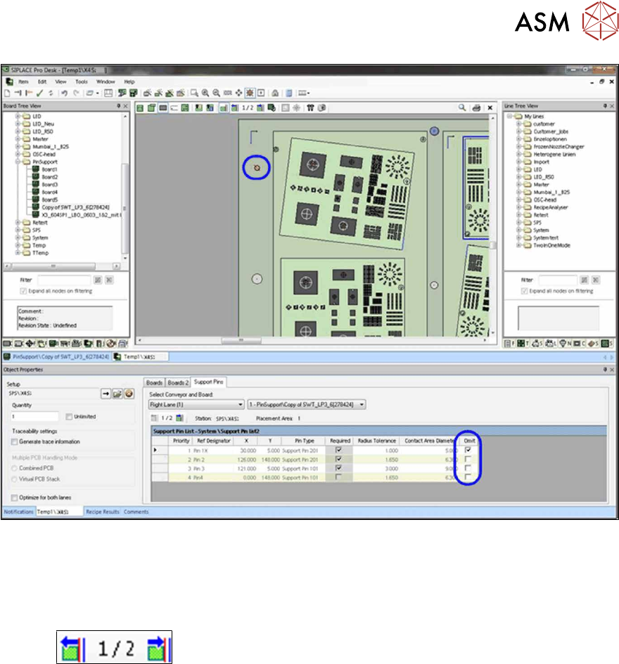
Recipe Editor – Setting production parameters for support pin positions
► If necessary, set the production parameter Omit for the support pin positions in the selected
placement area.
Omitted support pin positions are displayed in red in the graphic.
The support pin positions may be verified for each processing area in the recipe.
With the
button you can stop the board at each stopper position and in that way
move the board through the whole line.