00197001-04_UM_Smart_Pin_Support_X-Series-S_SX12V2_DE_EN.pdf - 第69页
2 Starting Hardware and Software 2.1 Performing Calibration User Manual / Bedienungsanleitung SIPLACE X-Series S, SX1/SX2 V2 Smart Pin Support Operation and Configura- tion 05/2019 69 2.1 Performing Calibration After ass…
2 Starting Hardware and Software
68 User Manual / Bedienungsanleitung SIPLACE X-Series S, SX1/SX2 V2 Smart Pin Support Operation and Configura-
tion 05/2019
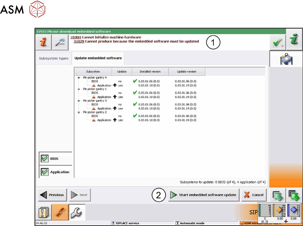
Fig.7: Update embedded software
► In this case, click on the Start embedded software update button (2)to download and up-
date the embedded software.
► Restart the machine.

2 Starting Hardware and Software
2.1 Performing Calibration
User Manual / Bedienungsanleitung SIPLACE X-Series S, SX1/SX2 V2 Smart Pin Support Operation and Configura-
tion 05/2019
69
2.1 Performing Calibration
After assembly, the pin picker, the pin magazine(s) and the lifting table(s) have to be calibrated.
Prerequisites
●
A support pin has to be present in the pin picker.
●
The garage to be calibrated in the pin magazine has to be empty.
Calibrating Procedure for Pin Picker and Lifting Table(s)
●
The gantry is moved to an X-/Y-position that is situated sufficiently far away from the conveyor
rails. This is performed four times during the lifting table calibration in order to determine the
angle of the conveyor.
●
After positioning the gantry, the electromagnet is switched on. This reduces the magnetic re-
tention force.
●
The valve for the support pin cylinder and the air kiss are switched on and the pin picker
moves downwards.
●
The air kiss cleans the lifting table during the movement downwards and the support pin is
placed.
●
The electromagnet is switched off.
●
The pin picker moves upwards and the air kiss for the support pin is switched off.
●
The gantry moves and is positioned with the PCB camera over the support pin.
●
A Vision measurement is performed and the support pin is detected.
●
The pin offset is corrected with the currently measured data and is saved.
●
The support pin position is measured again for checking purposes.
●
After that, the electromagnet is switched on and the support pin is picked up again.
●
The pin picker moves upwards and the electromagnet is switched off again.
●
The support pin remains in the pin picker.
Calibrating Procedure for Pin Magazine(s)
●
The support pin in the pin picker is detected and the two fiducials in the pin magazine are
measured.
●
It is checked whether a support pin is present in the garage into which the support pin shall be
put back afterwards.
●
After positioning the gantry, the electromagnet is switched on. This reduces the magnetic re-
tention force.
●
The valve for the support pin cylinder and the air kiss are switched on and the pin picker
moves downwards.
●
A cleaning procedure by air kiss is initiated for the pin magazine during the movement down-
wards and the support pin is put back into the garage.
●
The electromagnet is switched off.
●
The pin picker moves upwards and the air kiss for the support pin is switched off.
●
The support pin is measured.
●
The pin offset is corrected and saved with the currently measured values (x, y and angle).
●
After that, the electromagnet is switched on and the support pin is picked up again.
●
The pin picker moves upwards and the electromagnet is switched off again.
●
The support pin remains in the pin picker.
2 Starting Hardware and Software
2.1 Performing Calibration
70 User Manual / Bedienungsanleitung SIPLACE X-Series S, SX1/SX2 V2 Smart Pin Support Operation and Configura-
tion 05/2019
2.1.1 Calibrating Pin Picker, Lifting Table(s) and Pin Magazine(s)
► Start the Automatic Calibration in the Service view of the station software.
In the following dialog box you are prompted to select the required calibration steps.
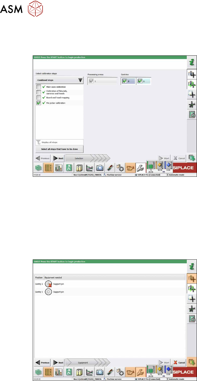
Fig.8: Selecting the pin picker
► Select Select all steps that have to be done.
or
► Select Select calibration steps → Combined steps → Pin picker calibration.
► Select Gantries.
► Click Next.
ð The conveyor width is automatically set correctly, i.e. so that at least one support pin can
be placed on every lifting table.
The following dialog box will appear if a support pin is missing:
Fig.9: Notification: Support pin missing
► Open the cover.
► Put the support pin into the pin picker.
► Close the cover.
► Click on the Continue button.