00197001-04_UM_Smart_Pin_Support_X-Series-S_SX12V2_DE_EN.pdf - 第95页
4 Working with Smart Pin Support at the Station 4.1 Smart Pin Support Setup View User Manual / Bedienungsanleitung SIPLACE X-Series S, SX1/SX2 V2 Smart Pin Support Operation and Configura- tion 05/2019 95 4 Working with …
3 Configuring Smart Pin Support in SIPLACE Pro
3.4 Download to the Station
94 User Manual / Bedienungsanleitung SIPLACE X-Series S, SX1/SX2 V2 Smart Pin Support Operation and Configura-
tion 05/2019
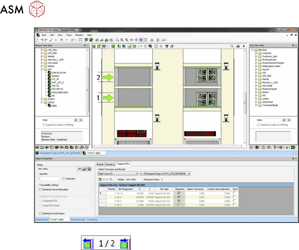
Fig.36: Recipe Editor - Move the board through the line (sample X4iS)
► Click on the
button to move the board to the next stopper position.
► Tick the support pin positions in all processing areas as described above.
The markings for the support pin positions are saved for each processing area.
3.4 Download to the Station
Prerequisite
●
The Smart Pin Support function has to be configured and activated for the station in the Setup
Editor as described in section 3.1 "Configuring Smart Pin Support in the Setup Editor " [}74].
The defined support pin positions and their properties (such as support pin type, Required, toler-
ance radius etc.) are sent to the station via the Converter of Line Control when the corresponding
recipe is downloaded at the station.
The order of the downloaded support pin positions corresponds to the order in the support pin list.
The order is handled by the priority setting as follows:
All support pin positions that are ticked as Required have the highest priority in the order of the pri-
ority setting, followed by the other positions in the order of the priority setting.
4 Working with Smart Pin Support at the Station
4.1 Smart Pin Support Setup View
User Manual / Bedienungsanleitung SIPLACE X-Series S, SX1/SX2 V2 Smart Pin Support Operation and Configura-
tion 05/2019
95
4 Working with Smart Pin Support at the Station
The Smart Pin Support function is supported by the station software as of the 706.0 version.
Prerequisites
●
The steps and prerequisites described in the preceding chapters have been performed and/or
are complied with.
●
The station is ready for operation.
●
A job with a setup containing a board with defined support pin positions has been defined in
SIPLACE Pro and downloaded to the station.
●
It is assumed that the support pins were automatically detected in the Autoconfiguration and
that the operator does not have to initiate special actions for the support pin positioning.
4.1 Smart Pin Support Setup View
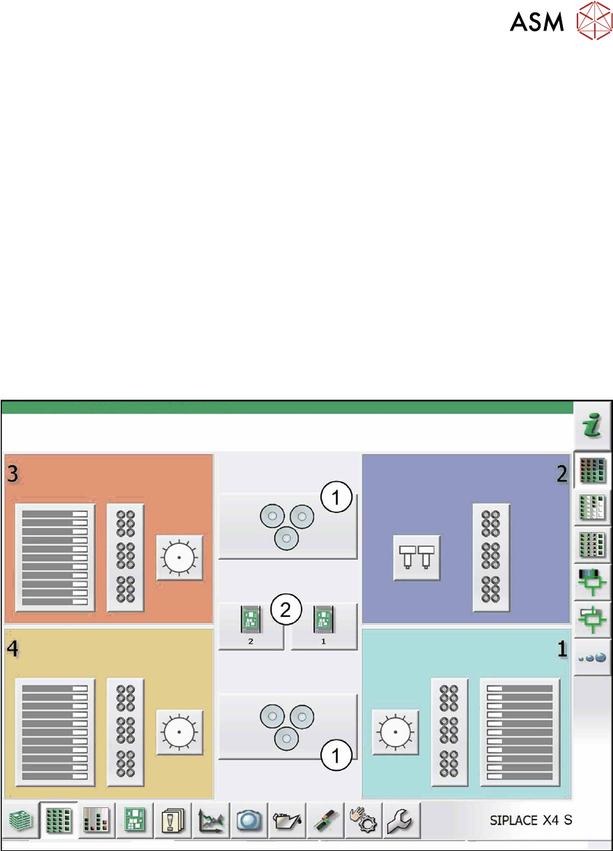
► Switch to the Feeders, components and nozzles view.
► Switch to the Setup - Locations view.
The following dialog box will open.
Fig.37: Setup – Locations (sample X4 S)
In the center, the Smart Pin Support Setup (1) will be displayed either below and/or above the
conveyor button (2).
► Click on the Smart Pin Support Setup button (1).
The following dialog box will open.
4 Working with Smart Pin Support at the Station
4.1 Smart Pin Support Setup View
96 User Manual / Bedienungsanleitung SIPLACE X-Series S, SX1/SX2 V2 Smart Pin Support Operation and Configura-
tion 05/2019
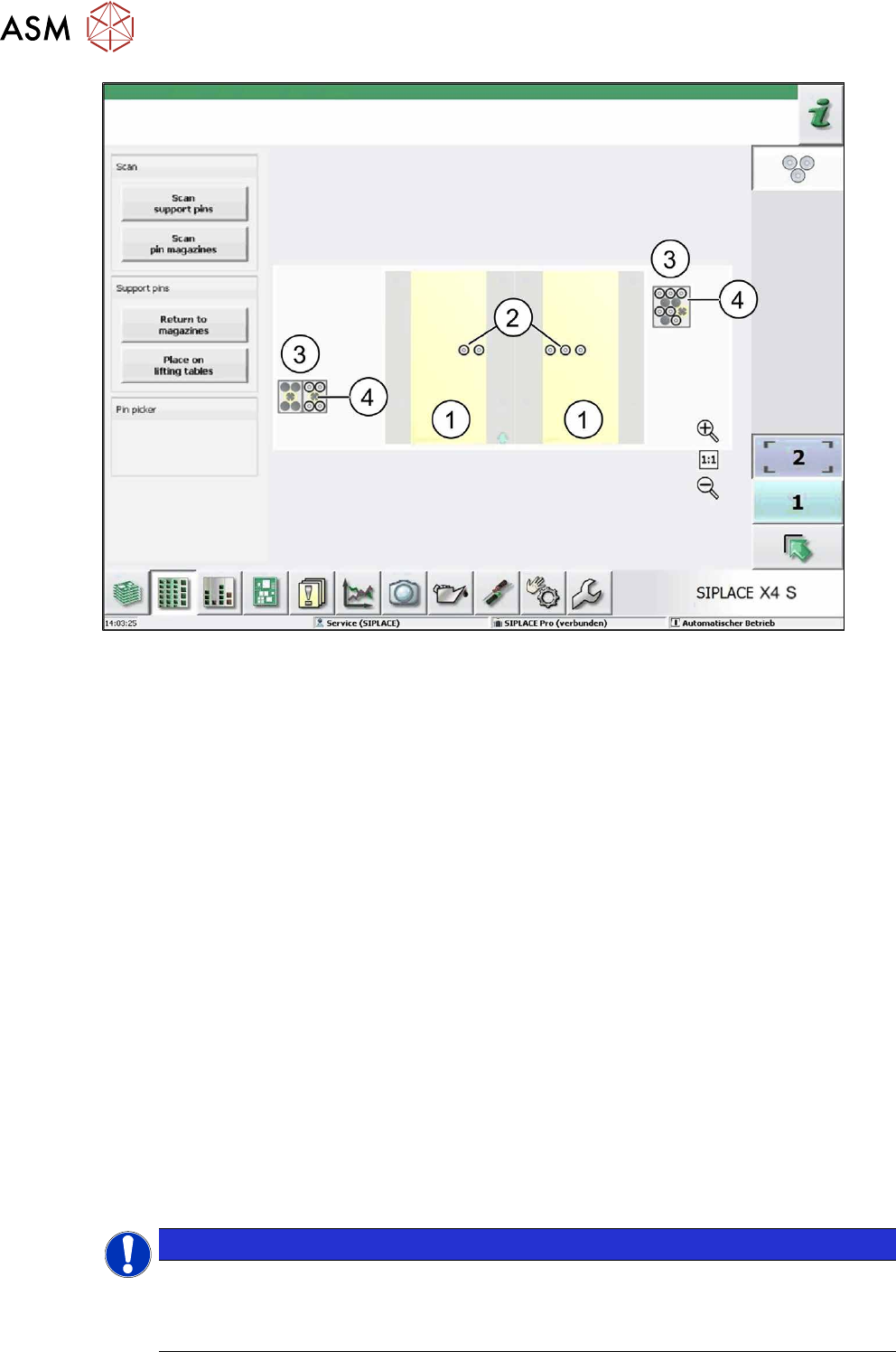
Fig.38: Support pins in processing area 1 (sample X4 S)
This view will be displayed per placement area. The yellow area (1) will display the area on the lift-
ing table on which support pins may be placed. On the lifting table the set support pin positions (2)
will be displayed with the existing support pins.
The support pin positions will be marked with crosshairs in different colors (see section 4.4 "Testing
Placement Head with Pin Picker Manually" [}100], figure Support pin functions tab (sample SX2)):
●
Green: a support pin is present at the support pin position
●
Red: no support pin at the support pin position
●
Gray: the support pin position is notmandatory (optional)
The garages (3) and the available support pins (4) will be displayed for the pin magazines.
The Smart Pin Support Setup view is updated dynamically. This means, whenever an action was per-
formed in the view or a change was registered by the monitoring software, an updated view will appear.
The following functions are provided in this view:
●
Scan support pins
The support pins on the lifting table and in the pin magazine will be scanned with the PCB camera.
●
Scan pin magazines
The garages will be scanned with the PCB camera.
●
Return to magazines
All support pins will be removed from the lifting table and placed back into the pin magazines.
●
Place on lifting tables
Support pins will be placed on the lifting tables.
Detailed information about the functions can be found in the Online Help for the station software.
Normally, no further actions are required by the operator. The Smart Pin Support job will be per-
formed automatically.
NOTICE
New behavior as of station software V707.0 and SIPLACE Pro V11.1
If an existing pin configuration on the lifting table is to be replaced by a new pin configura-
tion, the pins will not be put back into the pin magazine. Instead, the existing pins will be
moved on the lifting table. This shortens the time for the configuration change.