00197001-04_UM_Smart_Pin_Support_X-Series-S_SX12V2_DE_EN.pdf - 第88页
3 Configuring Smart Pin Support in SIPLACE Pro 3.2 Defining Support Pin Positions in the Board Editor 88 User Manual / Bedienungsanleitung SIPLACE X-Series S, SX1/SX2 V2 Smart Pin Support Operation and Configura- tion 05…
3 Configuring Smart Pin Support in SIPLACE Pro
3.2 Defining Support Pin Positions in the Board Editor
User Manual / Bedienungsanleitung SIPLACE X-Series S, SX1/SX2 V2 Smart Pin Support Operation and Configura-
tion 05/2019
87
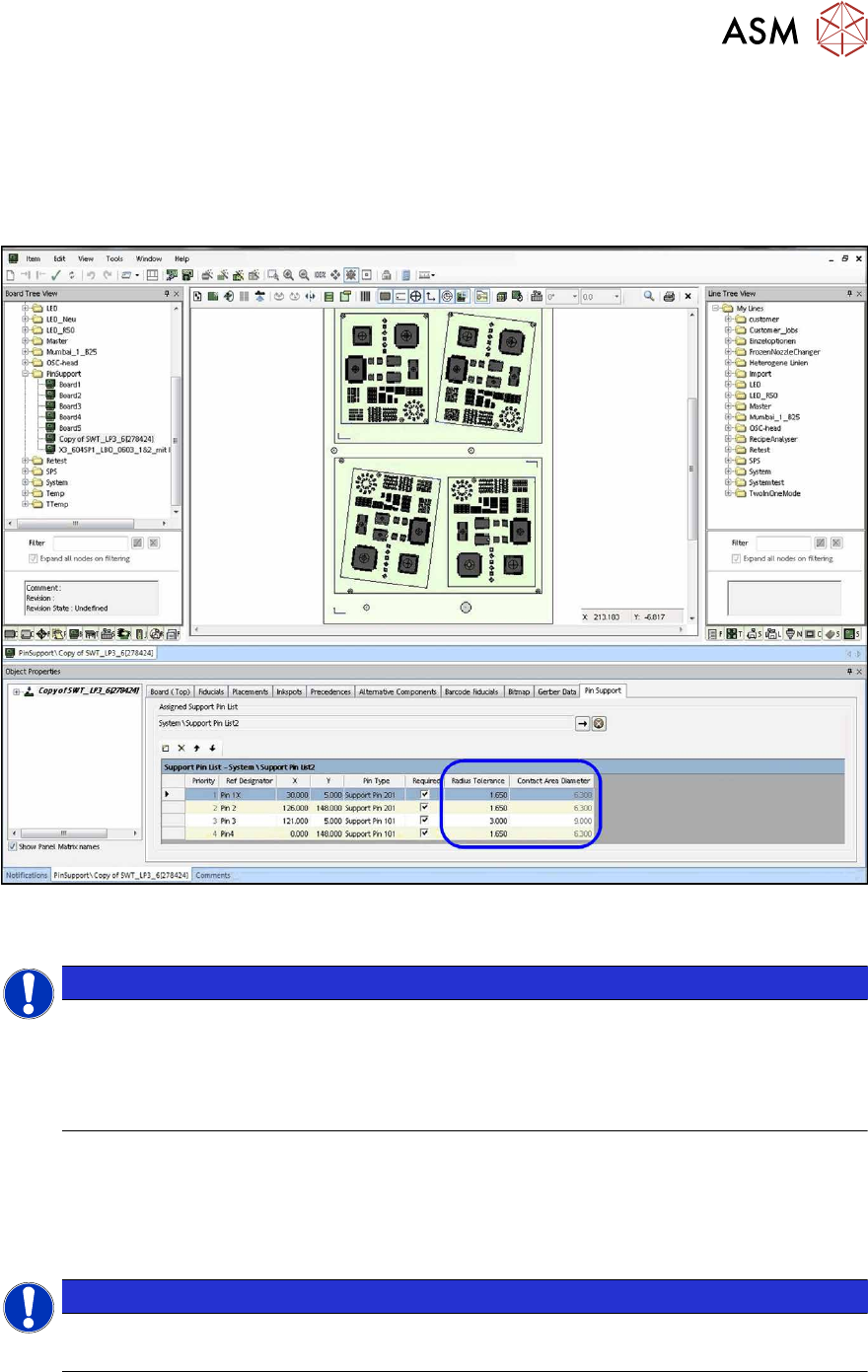
3.2.2.7 Defining Tolerance Radius
The defined tolerance radius determines the contact area within which the support pin may touch
the board. If zero is defined as tolerance radius, a minimum contact area remains. This is displayed
in the Contact Area Diameter field. The tolerance radius is displayed as a circle around the pin
position and is used by the station to mark a board for inspection if the board was clamped and
measured with a larger tolerance.
Fig.29: Defining tolerance radius
► Define the tolerance radius.
NOTICE
Tolerance size
The tolerance size should be carefully set and checked.
If the tolerance is set too small, it is probable that the board gets marked for inspection.
However, as a minimum tolerance is always warranted to make sure that the support pins
can be placed smoothly, no processing errors will be caused by possible collisions.
3.2.2.8 Saving Support Pin List
After you have defined all desired support pin positions for the board, these are automatically
saved in a support pin list.
► Accept the proposed name for the support pin list or enter a new name.
NOTICE
Using the support pin list
The saved support pin list can also be assigned to other boards.
3 Configuring Smart Pin Support in SIPLACE Pro
3.2 Defining Support Pin Positions in the Board Editor
88 User Manual / Bedienungsanleitung SIPLACE X-Series S, SX1/SX2 V2 Smart Pin Support Operation and Configura-
tion 05/2019
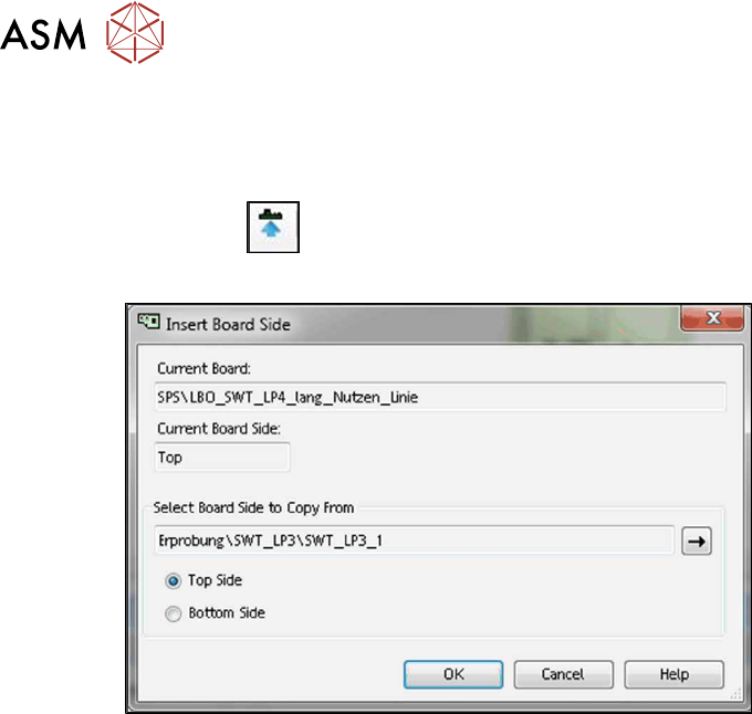
3.2.3 Adding Board Side
If a board is opened and a board side selected in the Board Editor, another board side can be
copied to this board.
Click on the
icon in the tool bar.
The Insert Board Side dialog box is opened.
Fig.30: Adding board side
► Select the board and the appropriate board side (Top Side or Bottom Side) to be copied.
► Click on OK to start copying.
The board side with all its properties and references is copied to the selected board / board side.
A warning is displayed if the target board side is not empty.
► Confirm the warning to overwrite the board side or cancel the copy process.
3 Configuring Smart Pin Support in SIPLACE Pro
3.2 Defining Support Pin Positions in the Board Editor
User Manual / Bedienungsanleitung SIPLACE X-Series S, SX1/SX2 V2 Smart Pin Support Operation and Configura-
tion 05/2019
89
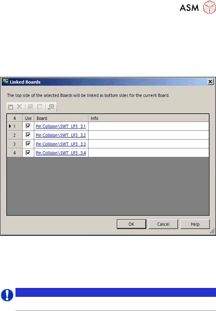
3.2.4 Linking Multiple Boards To Each Other
If different boards are used to define top side and underside of the board, these boards may now
be linked to each other for the collision check of the support pins, provided that no board underside
is defined for the currently selected board. Only the own underside or the top side of other boards
may be set as link for the board bottom side.
► Click on the Link Board Side Data button in the Board Editor.
The following dialog opens in which one or multiple boards may be selected or added to be dis-
played as board underside.
Fig.31: Linking boards to each other
The board top side of the selected board will be displayed as board underside of the current board
in the 3D view.
The board top side of the linked board will be displayed as board underside in the 2D view by click-
ing on the "Show underside" icon.
Single, linked boards can be hidden in the graphical view. For this, the checkmark has to be re-
moved from the Use field in the dialog box.
NOTICE
Art und Quelle der Gefahr
It is not possible to switch to the board underside if linked boards are selected.