00197001-04_UM_Smart_Pin_Support_X-Series-S_SX12V2_DE_EN.pdf - 第76页
3 Configuring Smart Pin Support in SIPLACE Pro 3.2 Defining Support Pin Positions in the Board Editor 76 User Manual / Bedienungsanleitung SIPLACE X-Series S, SX1/SX2 V2 Smart Pin Support Operation and Configura- tion 05…
3 Configuring Smart Pin Support in SIPLACE Pro
3.1 Configuring Smart Pin Support in the Setup Editor
User Manual / Bedienungsanleitung SIPLACE X-Series S, SX1/SX2 V2 Smart Pin Support Operation and Configura-
tion 05/2019
75
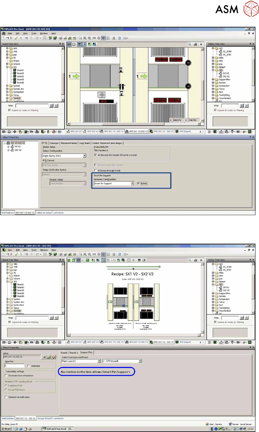
Fig.14: Setup Editor – Sample Smart Pin Support active (SX1)
In the Support Pins tab in the Recipe Editor it is then displayed whether the function is active or
inactive at the selected station.
Fig.15: Recipe Editor – Sample Smart Pin Support inactive (SX1 / SX2)
3 Configuring Smart Pin Support in SIPLACE Pro
3.2 Defining Support Pin Positions in the Board Editor
76 User Manual / Bedienungsanleitung SIPLACE X-Series S, SX1/SX2 V2 Smart Pin Support Operation and Configura-
tion 05/2019
3.2 Defining Support Pin Positions in the Board Editor
Prerequisites
●
SIPLACE Pro Desk (version 10.0 or higher) is started.
Preparatory Steps
► Open the Board Editor in SIPLACE Pro Desk.
► Open the board and board side for which you wish to define the support pin positions.
► Switch to the Pin Support tab.
NOTICE
Pin Support Tab
This tab is only displayed if a board side is selected in the tree view of the boards. A separ-
ate pin list is defined for each board side.
3.2.1 Pin Support Tab
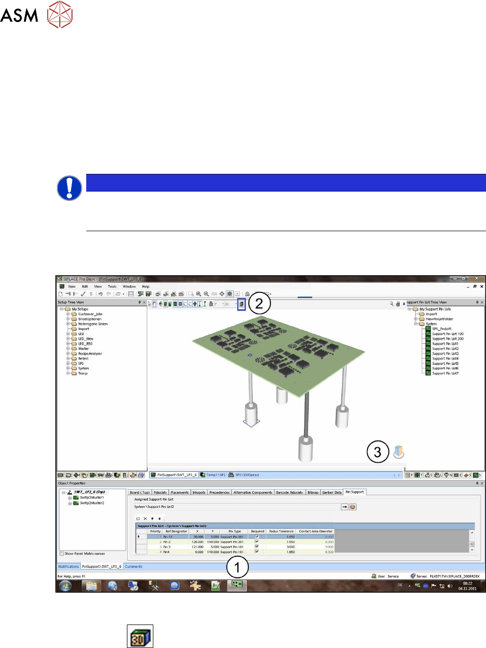
The following window displays a sample of the Pin Support tab.
Fig.16: Sample: Pin Support tab, board view
If the board side is selected in the tree view of the boards (1), the board can be displayed as a 3D
graphic with the
(2) button, in order to display the contact areas of the support pins on the
board underside as well. With the cube at the right bottom (3) you can switch between the views
(top/bottom). The 3D graphic is controlled via the mouse or the keyboard (see the Online help for
SIPLACE Pro). In the 2D graphic the support pins can be positioned via the mouse. By zooming
inside the view, the drawn support pins and their contact areas are distinctly visible. The selected
support pin list is displayed at the bottom of the window.
3 Configuring Smart Pin Support in SIPLACE Pro
3.2 Defining Support Pin Positions in the Board Editor
User Manual / Bedienungsanleitung SIPLACE X-Series S, SX1/SX2 V2 Smart Pin Support Operation and Configura-
tion 05/2019
77
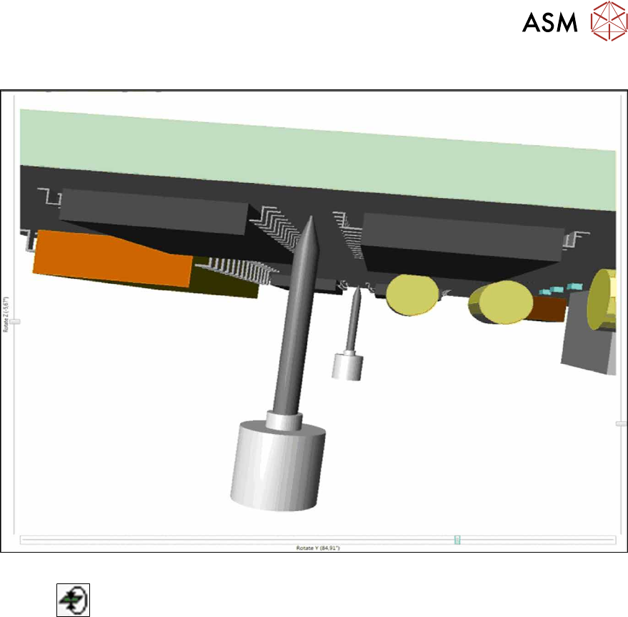
Sample: Zoom View
Fig.17: Sample: Zoom View
With the
button you can switch to a transparent view of the board to check defined support
pin positions on the board underside.