00197001-04_UM_Smart_Pin_Support_X-Series-S_SX12V2_DE_EN.pdf - 第70页
2 Starting Hardware and Software 2.1 Performing Calibration 70 User Manual / Bedienungsanleitung SIPLACE X-Series S, SX1/SX2 V2 Smart Pin Support Operation and Configura- tion 05/2019 2.1.1 Calibrating Pin Picker, Liftin…

2 Starting Hardware and Software
2.1 Performing Calibration
User Manual / Bedienungsanleitung SIPLACE X-Series S, SX1/SX2 V2 Smart Pin Support Operation and Configura-
tion 05/2019
69
2.1 Performing Calibration
After assembly, the pin picker, the pin magazine(s) and the lifting table(s) have to be calibrated.
Prerequisites
●
A support pin has to be present in the pin picker.
●
The garage to be calibrated in the pin magazine has to be empty.
Calibrating Procedure for Pin Picker and Lifting Table(s)
●
The gantry is moved to an X-/Y-position that is situated sufficiently far away from the conveyor
rails. This is performed four times during the lifting table calibration in order to determine the
angle of the conveyor.
●
After positioning the gantry, the electromagnet is switched on. This reduces the magnetic re-
tention force.
●
The valve for the support pin cylinder and the air kiss are switched on and the pin picker
moves downwards.
●
The air kiss cleans the lifting table during the movement downwards and the support pin is
placed.
●
The electromagnet is switched off.
●
The pin picker moves upwards and the air kiss for the support pin is switched off.
●
The gantry moves and is positioned with the PCB camera over the support pin.
●
A Vision measurement is performed and the support pin is detected.
●
The pin offset is corrected with the currently measured data and is saved.
●
The support pin position is measured again for checking purposes.
●
After that, the electromagnet is switched on and the support pin is picked up again.
●
The pin picker moves upwards and the electromagnet is switched off again.
●
The support pin remains in the pin picker.
Calibrating Procedure for Pin Magazine(s)
●
The support pin in the pin picker is detected and the two fiducials in the pin magazine are
measured.
●
It is checked whether a support pin is present in the garage into which the support pin shall be
put back afterwards.
●
After positioning the gantry, the electromagnet is switched on. This reduces the magnetic re-
tention force.
●
The valve for the support pin cylinder and the air kiss are switched on and the pin picker
moves downwards.
●
A cleaning procedure by air kiss is initiated for the pin magazine during the movement down-
wards and the support pin is put back into the garage.
●
The electromagnet is switched off.
●
The pin picker moves upwards and the air kiss for the support pin is switched off.
●
The support pin is measured.
●
The pin offset is corrected and saved with the currently measured values (x, y and angle).
●
After that, the electromagnet is switched on and the support pin is picked up again.
●
The pin picker moves upwards and the electromagnet is switched off again.
●
The support pin remains in the pin picker.
2 Starting Hardware and Software
2.1 Performing Calibration
70 User Manual / Bedienungsanleitung SIPLACE X-Series S, SX1/SX2 V2 Smart Pin Support Operation and Configura-
tion 05/2019
2.1.1 Calibrating Pin Picker, Lifting Table(s) and Pin Magazine(s)
► Start the Automatic Calibration in the Service view of the station software.
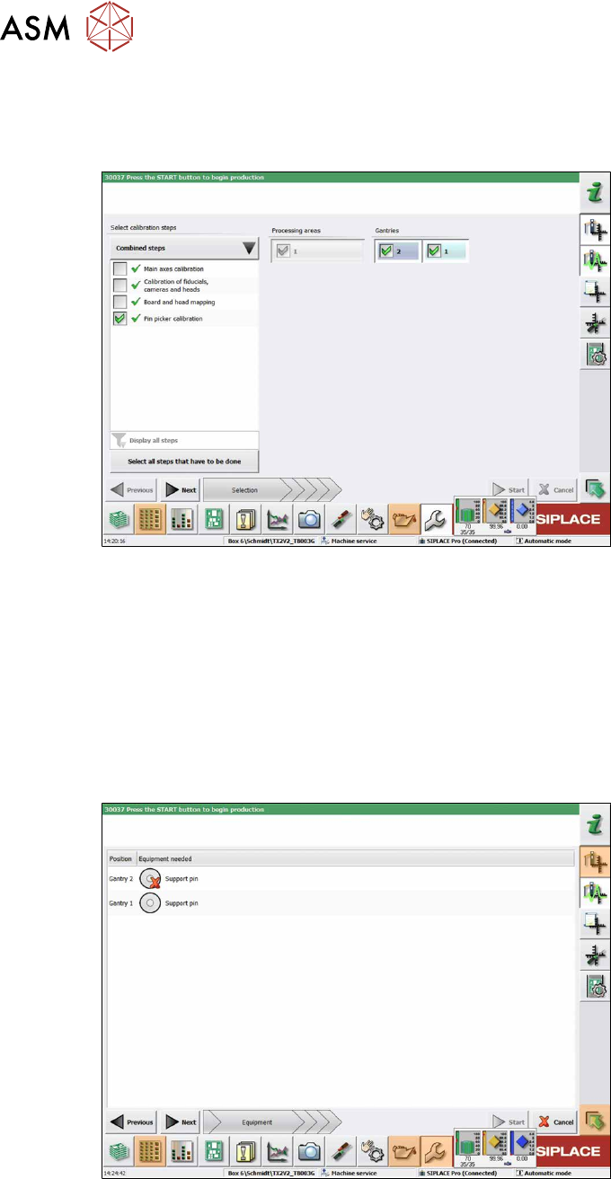
In the following dialog box you are prompted to select the required calibration steps.
Fig.8: Selecting the pin picker
► Select Select all steps that have to be done.
or
► Select Select calibration steps → Combined steps → Pin picker calibration.
► Select Gantries.
► Click Next.
ð The conveyor width is automatically set correctly, i.e. so that at least one support pin can
be placed on every lifting table.
The following dialog box will appear if a support pin is missing:
Fig.9: Notification: Support pin missing
► Open the cover.
► Put the support pin into the pin picker.
► Close the cover.
► Click on the Continue button.
2 Starting Hardware and Software
2.1 Performing Calibration
User Manual / Bedienungsanleitung SIPLACE X-Series S, SX1/SX2 V2 Smart Pin Support Operation and Configura-
tion 05/2019
71
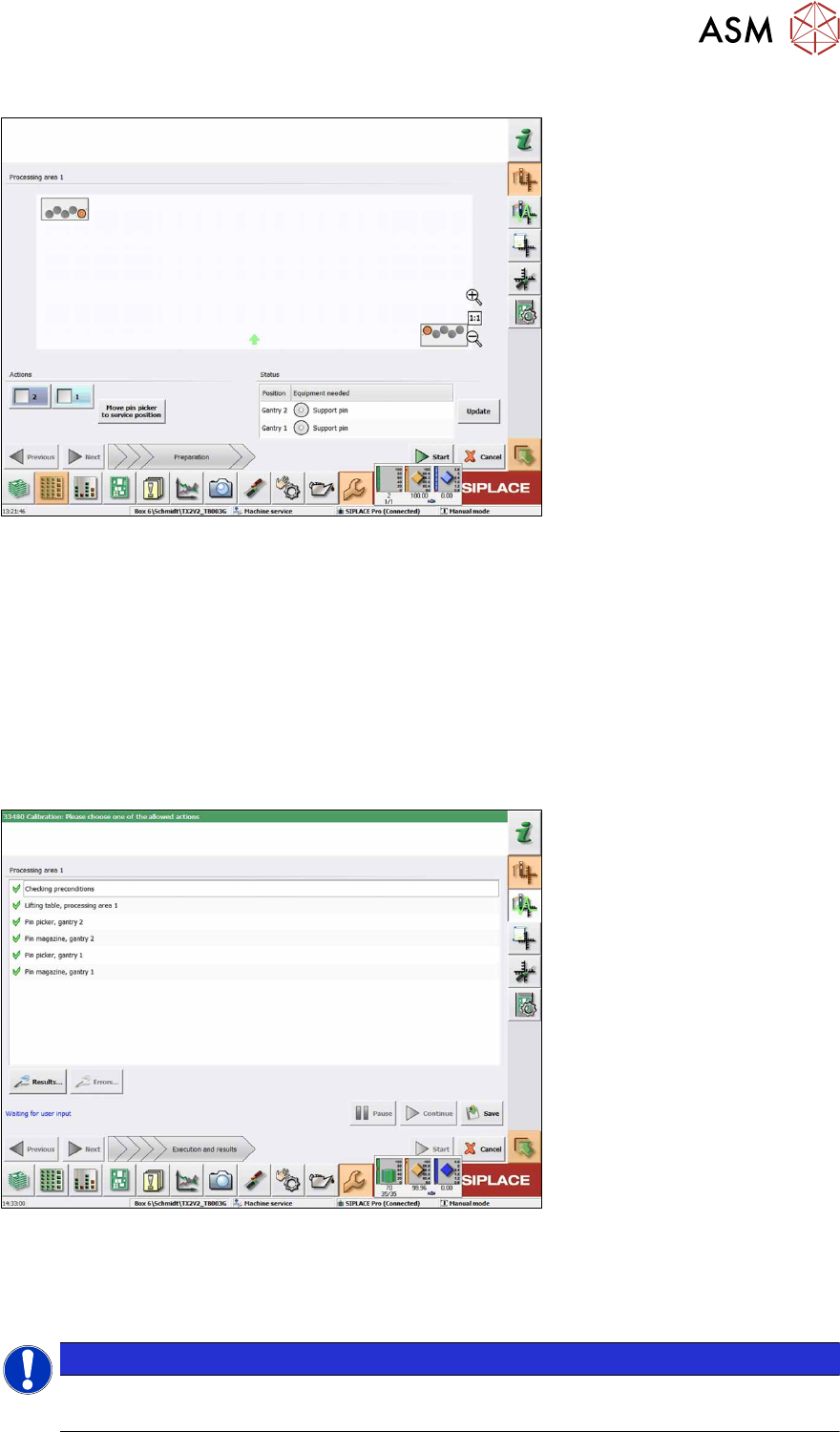
The following dialog box will appear if a calibration garage is occupied:
Fig.10: Notification: Calibration garage occupied
► Click on the Move pin picker to service position button.
The gantry moves to the service position for Smart Pin Support and you are prompted to remove
the support pin from the garage and put it into the pin picker.
► Open the cover.
► Remove the support pin from the calibration garage.
► Close the cover.
► Click on the Continue button.
► Once all preconditions have been fulfilled, click on the Start button.
In the following dialog box the calibration result is displayed.
Fig.11: Saving the calibration
► Click on the Results… for details button.
► Click on the Save button to apply the calibration data.
► Click on the Close button to exit the calibration.
NOTICE
Filling the magazines
After having been successfully calibrated, the magazines may be filled with support pins.