00197001-04_UM_Smart_Pin_Support_X-Series-S_SX12V2_DE_EN.pdf - 第68页
2 Starting Hardware and Software 68 User Manual / Bedienungsanleitung SIPLACE X-Series S, SX1/SX2 V2 Smart Pin Support Operation and Configura- tion 05/2019 Fig.7: Update embedded software ► In this case, click on the…
2 Starting Hardware and Software
User Manual / Bedienungsanleitung SIPLACE X-Series S, SX1/SX2 V2 Smart Pin Support Operation and Configura-
tion 05/2019
67
2 Starting Hardware and Software
The following requirements must be met before the hardware and software can be started:
Requirements
●
The pin magazine has been installed and correctly adjusted at the designated location in the
placement machine.
●
The pin picker has been installed at the gantry and is connected to the head board.
Detailed information can be found in the Smart Pin Support Assembly Instructions, item no.
[00197002-xx].
► Ensure that the calibration garage is empty.
► Put a support pin into the pin picker.
► Switch the placement machine on.
These steps and what has to be considered are described in detail in the User Manual for the
placement machines.
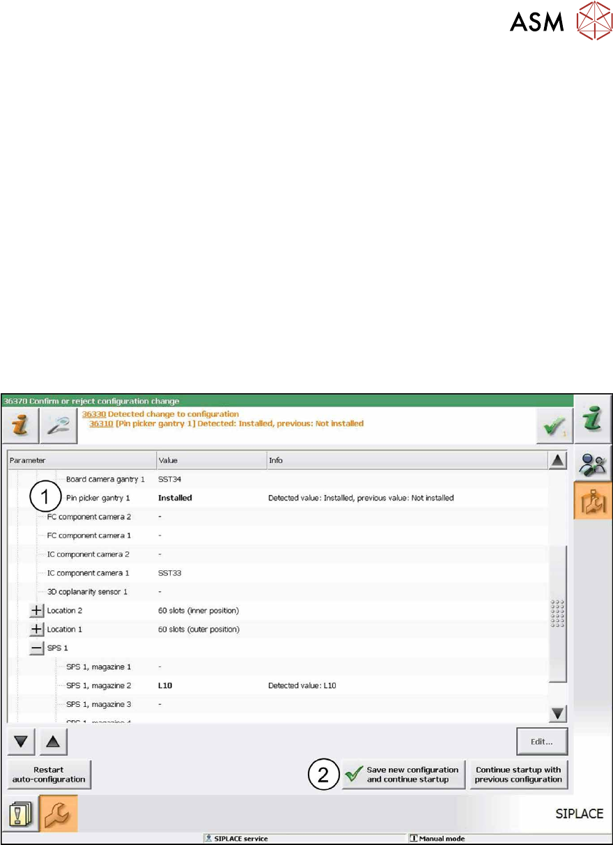
The pin picker is automatically detected in the Autoconfiguration (1). The reference run is being
executed. After the reference run has been completed the station is ready for operation.
Fig.6: Saving configuration
► Click on the Save new configuration and continue startup button (2) to save the new con-
figuration.
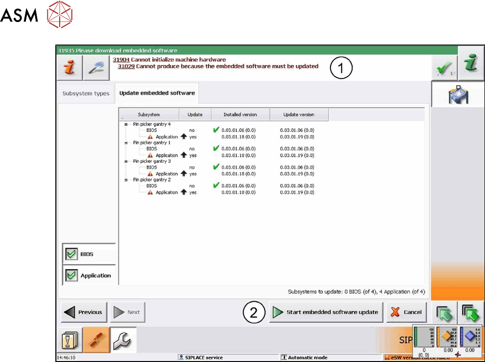
If the embedded software is not up-do-date a corresponding hint(1) informs you that the embed-
ded software has to be updated and downloaded.
2 Starting Hardware and Software
68 User Manual / Bedienungsanleitung SIPLACE X-Series S, SX1/SX2 V2 Smart Pin Support Operation and Configura-
tion 05/2019
Fig.7: Update embedded software
► In this case, click on the Start embedded software update button (2)to download and up-
date the embedded software.
► Restart the machine.

2 Starting Hardware and Software
2.1 Performing Calibration
User Manual / Bedienungsanleitung SIPLACE X-Series S, SX1/SX2 V2 Smart Pin Support Operation and Configura-
tion 05/2019
69
2.1 Performing Calibration
After assembly, the pin picker, the pin magazine(s) and the lifting table(s) have to be calibrated.
Prerequisites
●
A support pin has to be present in the pin picker.
●
The garage to be calibrated in the pin magazine has to be empty.
Calibrating Procedure for Pin Picker and Lifting Table(s)
●
The gantry is moved to an X-/Y-position that is situated sufficiently far away from the conveyor
rails. This is performed four times during the lifting table calibration in order to determine the
angle of the conveyor.
●
After positioning the gantry, the electromagnet is switched on. This reduces the magnetic re-
tention force.
●
The valve for the support pin cylinder and the air kiss are switched on and the pin picker
moves downwards.
●
The air kiss cleans the lifting table during the movement downwards and the support pin is
placed.
●
The electromagnet is switched off.
●
The pin picker moves upwards and the air kiss for the support pin is switched off.
●
The gantry moves and is positioned with the PCB camera over the support pin.
●
A Vision measurement is performed and the support pin is detected.
●
The pin offset is corrected with the currently measured data and is saved.
●
The support pin position is measured again for checking purposes.
●
After that, the electromagnet is switched on and the support pin is picked up again.
●
The pin picker moves upwards and the electromagnet is switched off again.
●
The support pin remains in the pin picker.
Calibrating Procedure for Pin Magazine(s)
●
The support pin in the pin picker is detected and the two fiducials in the pin magazine are
measured.
●
It is checked whether a support pin is present in the garage into which the support pin shall be
put back afterwards.
●
After positioning the gantry, the electromagnet is switched on. This reduces the magnetic re-
tention force.
●
The valve for the support pin cylinder and the air kiss are switched on and the pin picker
moves downwards.
●
A cleaning procedure by air kiss is initiated for the pin magazine during the movement down-
wards and the support pin is put back into the garage.
●
The electromagnet is switched off.
●
The pin picker moves upwards and the air kiss for the support pin is switched off.
●
The support pin is measured.
●
The pin offset is corrected and saved with the currently measured values (x, y and angle).
●
After that, the electromagnet is switched on and the support pin is picked up again.
●
The pin picker moves upwards and the electromagnet is switched off again.
●
The support pin remains in the pin picker.