00197001-04_UM_Smart_Pin_Support_X-Series-S_SX12V2_DE_EN.pdf - 第63页
1 Introduction 1.1 Safety Instructions User Manual / Bedienungsanleitung SIPLACE X-Series S, SX1/SX2 V2 Smart Pin Support Operation and Configura- tion 05/2019 63 1 Introduction These instructions describe the configurat…

62 User Manual / Bedienungsanleitung SIPLACE X-Series S, SX1/SX2 V2 Smart Pin Support Operation and Configura-
tion 05/2019
Contents
5 Sample Applications.. 105
5.1 Support pin placement.. 105
5.1.1 Not enough support pins.. 105
5.1.2 Support Pin Is Missing on the Lifting Table.. 106
5.2 Smart Pin Support and Long Board Option - (LBO).. 108
5.3 Smart Pin Support and PCB Barcode Mode.. 110
6 Restrictions.. 111
1 Introduction
1.1 Safety Instructions
User Manual / Bedienungsanleitung SIPLACE X-Series S, SX1/SX2 V2 Smart Pin Support Operation and Configura-
tion 05/2019
63
1 Introduction
These instructions describe the configuration and operation of the Smart Pin Support function at
the SIPLACE© SX1/SX2 V2 and SIPLACE X-Series S placement machines (except for SIPLACE
X2 S).
1.1 Safety Instructions
DANGER
Nonobservance of these safety instructions may cause injury to personnel and dam-
age to the machine!
► Please observe the safety instructions in the instruction manualof our machine for
all work!
1.1.1 Conventions for the use of safety instructions and symbols
Safety instructions
This manual contains notes that must be observed to guarantee your personal safety and to avoid
damage to equipment. These notes are highlighted by warning triangles and are indicated as fol-
lows according to the level of risk:
DANGER
Definition
For the purposes of this manual, this indicates that fatal or severe injuries or considerable
damage to property will occur if this hazard warning is not observed.
WARNING
Definition
For the purposes of this manual, this indicates that fatal or severe injuries or considerable
damage to equipment may occur if these warning instructions are not followed.
CAUTION
Definition
For the purposes of this manual, this indicates that minor injuries or damage to property
may occur if this caution is not observed.
NOTICE
Definition
For the purposes of this manual, this note provides information about the product or indic-
ates a part of the manual that requires particular attention.
Symbols
Example Description
Next This typeface marks controls and interface elements in the software.
► This symbol indicates actions that have to be performed by the operator.
1 Introduction
1.2 Brief Description
64 User Manual / Bedienungsanleitung SIPLACE X-Series S, SX1/SX2 V2 Smart Pin Support Operation and Configura-
tion 05/2019
1.2 Brief Description
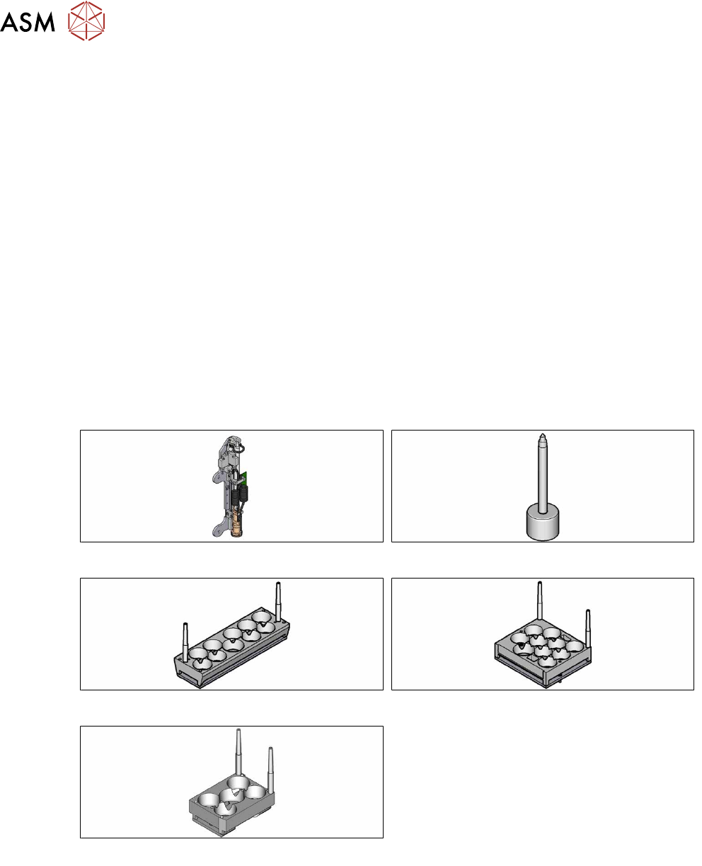
For many products it is necessary to support the board with so-called Support Pins in the pro-
cessing area.
The support pins are placed on the lifting table and are kept at the defined position by a magnet.
This pin positioning can be automatically performed with the SIPLACE© Smart Pin Support func-
tion for the following placement machines:
●
SIPLACE SX1/SX2 V2
●
SIPLACE X-seriesS (except for SIPLACE X2 S)
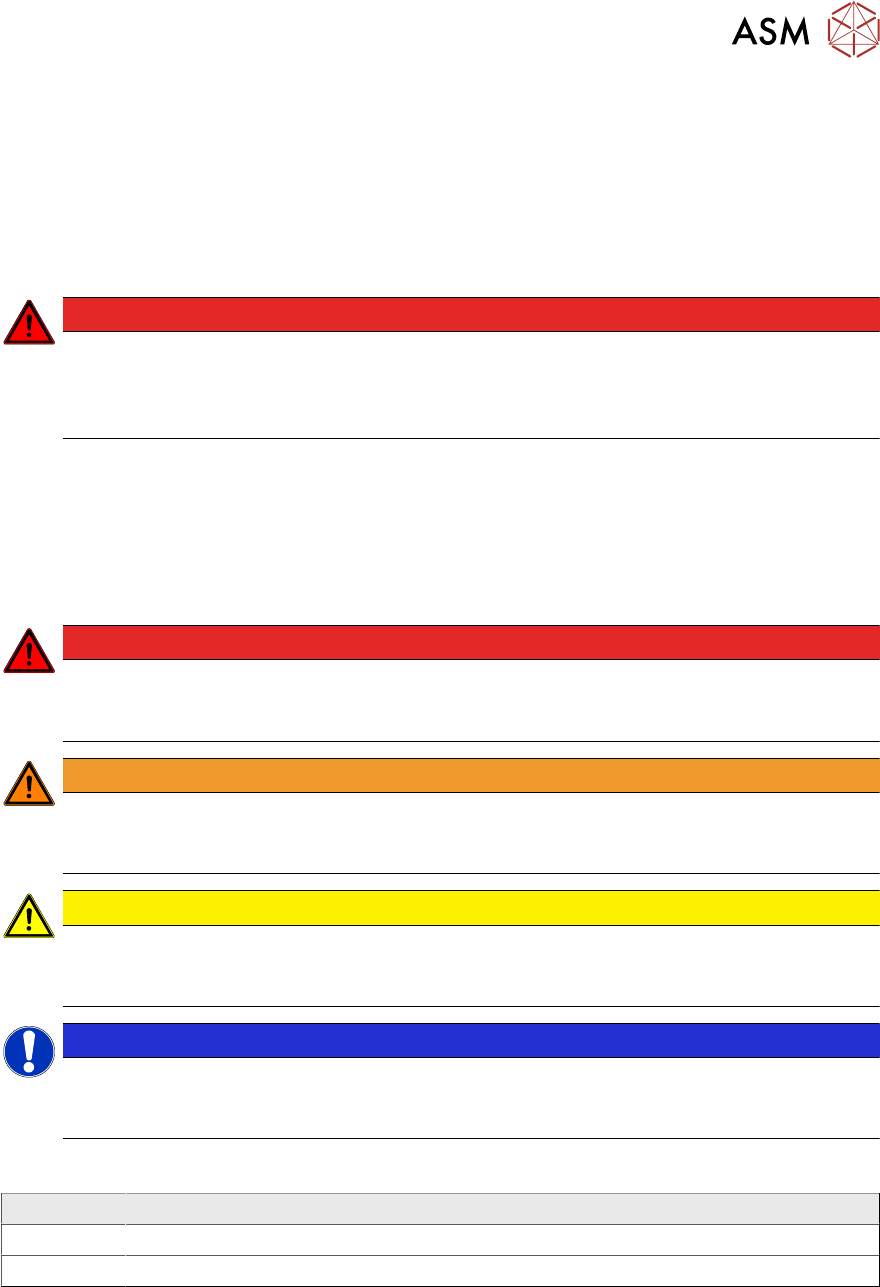
The support pin positioning is performed by a pin picker that is installed at the placement head and
is able to place a definable number of support pins on the lifting table.
The support pins are picked up from the garages of the pin magazines (L10, Q10 or W5).
The support pin positions are defined for a board and a recipe in SIPLACE Pro. When the recipe is
produced at the placement line, the support pins will be positioned fully automatically.
This document describes how to define and configure the automatic support pin positioning in
SIPLACE Pro and modify the settings for Smart Pin Support in the station software.
In addition, application examples and workflows show how to handle problems with Smart Pin Sup-
port and use the support pin positioning in combination with PCB barcode mode and the Long
Board Option (LBO).
Fig.1: Pin picker
Fig.2: Support pin
Fig.3: Pin magazine L10
Fig.4: Pin magazine Q10
Fig.5: Pin magazine W5