00197001-04_UM_Smart_Pin_Support_X-Series-S_SX12V2_DE_EN.pdf - 第109页
5 Sample Applications 5.2 Smart Pin Support and Long Board Option - (LBO) User Manual / Bedienungsanleitung SIPLACE X-Series S, SX1/SX2 V2 Smart Pin Support Operation and Configura- tion 05/2019 109 Fig.50: Recipe Edito…
5 Sample Applications
5.2 Smart Pin Support and Long Board Option - (LBO)
108 User Manual / Bedienungsanleitung SIPLACE X-Series S, SX1/SX2 V2 Smart Pin Support Operation and Configura-
tion 05/2019
5.2 Smart Pin Support and Long Board Option - (LBO)
The following example displays how to combine Smart Pin Support and the Long Board Option
(LBO) with each other.
Requirements:
●
A setup in which stations with configured LBO support are present.
●
A support pin list with support pins is assigned to the board.
●
The Long Board Option must be enabled in the Line Editor. After that, the offset for the LBO
stopper may be corrected in the Setup Editor under the Long Board tab.
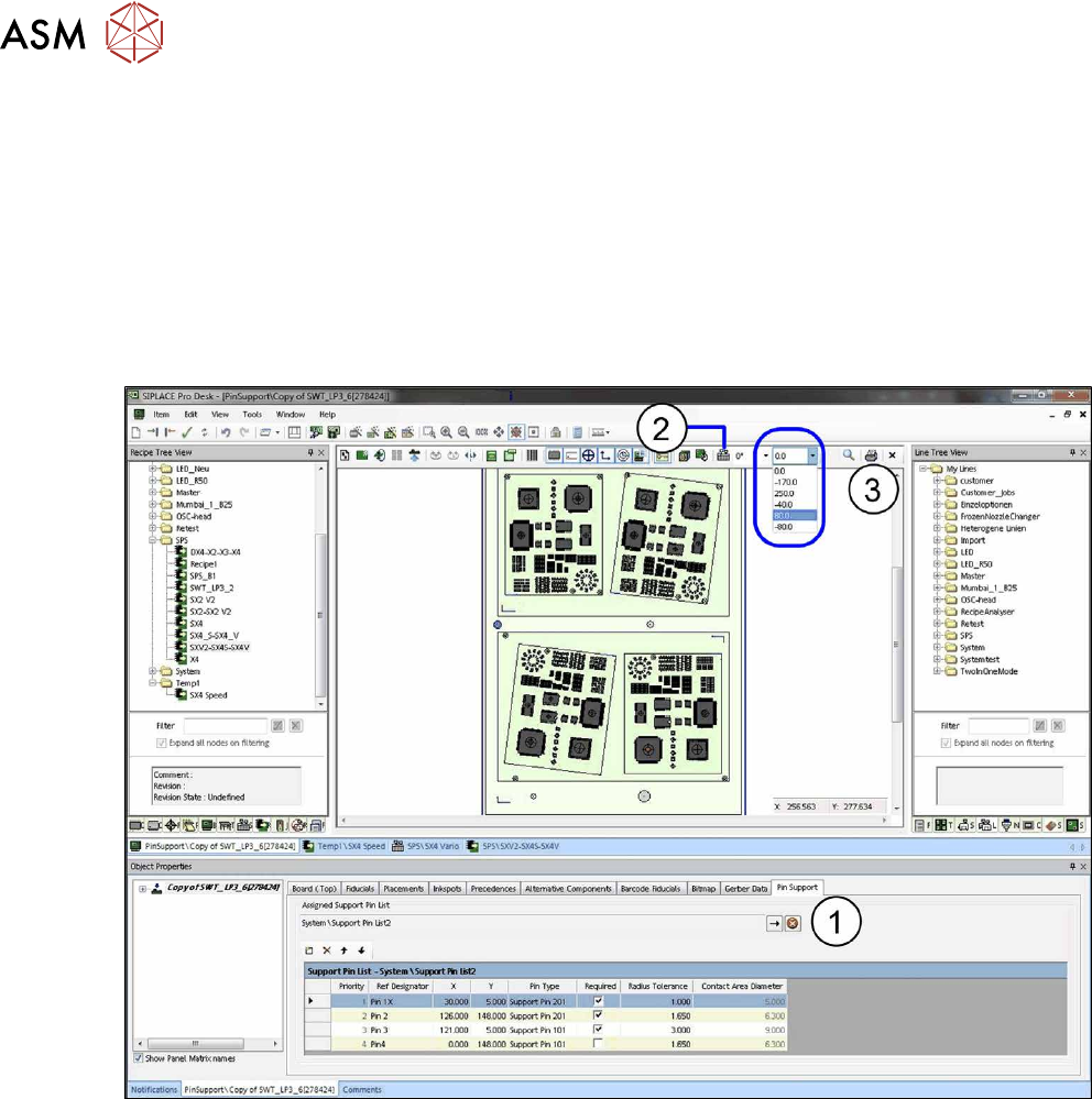
Fig.49: Board Editor: LBO setup
► Open the Board Editor and select the Pin Support tab(1).
► Click on the Setup icon(2).
The stopper positions that have been defined in the setup will be displayed in a drop down list(3).
► Select the desired stopper positions in relation to the board from the drop down list.
The support pins will be adjusted accordingly.
► Make sure that the support pins at the different support pin positions do not collide with the
components.
If the board is moved into the machine with a different than 0°, another angle value may be set in
the tool bar and the offset checked with other angle values.
5 Sample Applications
5.2 Smart Pin Support and Long Board Option - (LBO)
User Manual / Bedienungsanleitung SIPLACE X-Series S, SX1/SX2 V2 Smart Pin Support Operation and Configura-
tion 05/2019
109
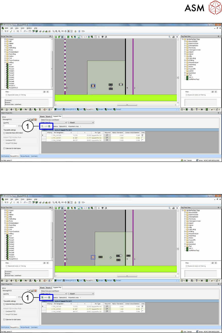
Fig.50: Recipe Editor: board in stopper position 1
In the Recipe Editor, the support pin positions will be displayed in the different stopper positions.
By clicking on the (1) icons (back and forwards) all stopper positions of the board within the line
can be displayed and visually checked.
Fig.51: Recipe Editor: board in stopper position 2
After the job has been downloaded at the station, the long board will be moved in and placed at the
first stopper position. After that, it will be moved to the second stopper position and placed again.
During positioning from the first to the second stopper position, no support pins can be placed or
adjusted on the lifting table.

5 Sample Applications
5.3 Smart Pin Support and PCB Barcode Mode
110 User Manual / Bedienungsanleitung SIPLACE X-Series S, SX1/SX2 V2 Smart Pin Support Operation and Configura-
tion 05/2019
5.3 Smart Pin Support and PCB Barcode Mode
In the following, a sample workflow at the station is displayed, when Smart Pin Support is used in
combination with PCB Barcode mode in asynchronous conveyor mode.
Prerequisites:
●
The jobs in PCB barcode mode are prepared in SIPLACE Pro as follows:
– Job 1: PCB1 with Barcode A -> Support pin list 1
– Job 2: PCB2 with Barcode B -> Support pin list 2
– Job 3: PCB3 with Barcode C -> Support pin list 3
●
Support pin positions are only changed if another pin position is loaded with a changed place-
ment program.
●
The station runs in asynchronous dual conveyor lane mode.
Workflow at the Station
●
Job 1 with PCB1 for Conveyor 1 is defined, the support pins from the Support pin list 1 are ad-
justed on the lifting table.
●
Job 1 with PCB1 for Conveyor 2 is defined, the support pins from the Support pin list 1 are ad-
justed on the lifting table.
●
PCB1 is moved into Conveyor 1: the PCB is moved to the processing area and gets placed.
●
PCB2 is moved into Conveyor 1: the PCB is moved into the input section.
●
While PCB1 in Conveyor 1 is still being placed, a PCB3 is moved into Conveyor 2: the PCB is
moved into the input section. The conveyor interface is disabled for both conveyor lanes.
●
When the placement of PCB1 in Conveyor 1 is completed, it is moved on and no PCB is
moved into the processing area.
●
The support pins from Support pin list 3 are completely adjusted on Conveyor 2:
The support pins on Conveyor 1 are adjusted from Support pin list 1 to Support pin list 2.
●
The boards in the input sections (Conveyor 1 and 2) are transported to the processing area
and get placed. The conveyor interface is enabled for both lanes again.
●
While PCB2 is still being placed in Conveyor 1, a PCB1 is moved in. PCB1 is moved into the
input section. As soon as PCB2 has been completely placed in the processing area, the sup-
port pins on Conveyor 1 will be adjusted from Support pin list 2 to Support pin list 1.
●
After the adjustment, PCB1 is transported from the input section to the processing area and
gets placed.
●
While PCB3 is still being placed in Conveyor 2, a PCB3 is moved in. PCB3 is moved into the
input section. As soon as PCB3 has been completely placed in the processing area, PCB3 is
moved from the input section into the processing area and gets placed.