00197001-04_UM_Smart_Pin_Support_X-Series-S_SX12V2_DE_EN.pdf - 第72页
2 Starting Hardware and Software 2.1 Performing Calibration 72 User Manual / Bedienungsanleitung SIPLACE X-Series S, SX1/SX2 V2 Smart Pin Support Operation and Configura- tion 05/2019 2.1.2 Handling Error Cases Error mes…
2 Starting Hardware and Software
2.1 Performing Calibration
User Manual / Bedienungsanleitung SIPLACE X-Series S, SX1/SX2 V2 Smart Pin Support Operation and Configura-
tion 05/2019
71
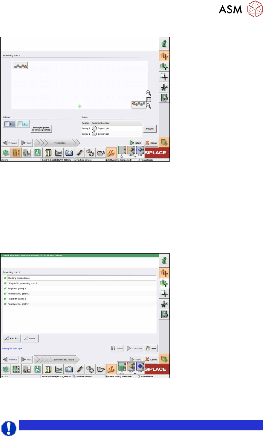
The following dialog box will appear if a calibration garage is occupied:
Fig.10: Notification: Calibration garage occupied
► Click on the Move pin picker to service position button.
The gantry moves to the service position for Smart Pin Support and you are prompted to remove
the support pin from the garage and put it into the pin picker.
► Open the cover.
► Remove the support pin from the calibration garage.
► Close the cover.
► Click on the Continue button.
► Once all preconditions have been fulfilled, click on the Start button.
In the following dialog box the calibration result is displayed.
Fig.11: Saving the calibration
► Click on the Results… for details button.
► Click on the Save button to apply the calibration data.
► Click on the Close button to exit the calibration.
NOTICE
Filling the magazines
After having been successfully calibrated, the magazines may be filled with support pins.

2 Starting Hardware and Software
2.1 Performing Calibration
72 User Manual / Bedienungsanleitung SIPLACE X-Series S, SX1/SX2 V2 Smart Pin Support Operation and Configura-
tion 05/2019
2.1.2 Handling Error Cases
Error message for support pin
If the support pin cannot be found (i.e. because it has slipped) or a fiducial for the support pin can-
not be detected (i.e. because soiled) you will be asked to confirm that the support pin has been
manually removed.
► Fix the error and restart the measurement.
The support pin is measured, the position is saved and the support pin is picked up again.
If you remove the support pin manually instead and confirm this, the calibrating procedure is can-
celed.
Error message for pin magazine(s)
If the station detects that a support pin is present in the garage, you are prompted to remove the
support pin.
► Remove the support pin from the garage.
► Confirm the message.
After that, the pin magazine calibration continues.
Error message for lifting table(s)
If other calibration steps than those for the Smart Pin Support function are performed and a map-
ping plate is required, a general message will be displayed that prompts you to remove support
pins from the lifting table. If support pins should be present on the lifting table, the calibration will be
canceled with a corresponding message.
► Remove the support pins from the lifting table.
► Confirm via the appropriate button that the support pins were removed and then restart the
measurement.
3 Configuring Smart Pin Support in SIPLACE Pro
User Manual / Bedienungsanleitung SIPLACE X-Series S, SX1/SX2 V2 Smart Pin Support Operation and Configura-
tion 05/2019
73
3 Configuring Smart Pin Support in SIPLACE
Pro
If a pin picker is installed at the station, it must be configured in the Setup Editor in SIPLACE Pro,
due to the fact that restrictions of the travel range are included in the calculation. An installed pin
picker can be deactivated for a station in SIPLACE Pro.
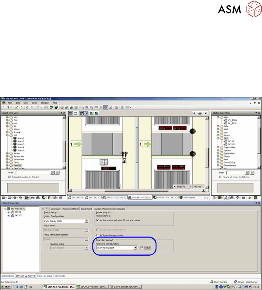
In order to use the Smart Pin Support function, the Smart Pin Support hardware option must be
activated in the Setup Editor.
Fig.12: Setup Editor – Smart Pin Support active
The pin positions must be defined in the Board Editor in SIPLACE Pro. Properties such as pin
name, pin type, X-/Y-position and tolerance radius are defined for these pin positions. By means of
a 3D and 2D view, the position of the support pins can be checked on both board sides (if top side
and underside are specified for the board) with respect to a potential collision with the components.
The pin positions are saved in a separate pin list. This pin list can also be used for other boards.
In the Recipe Editor the settings of the pin positions will then be displayed for each placement area
in the setup. The operator can switch between the top side and underside of the board. If required,
the Omit property can be set for each pin position.
The saved pin lists are displayed in a separate tree view in which they may be moved, copied or
deleted. Switch to the Board Editor to open a pin list.
The defined pin positions and their properties will be sent to the station via the GUI Converter of
Line Control when the corresponding recipe is downloaded at the station.