00191369-01.pdf - 第164页
5 Single Functions User’s Manual SIPLACE HS-50 5.2 Single functions, G antry Software Version SR.501.xx Edi tion 01/99 162 1R]]OHFRQILJXUDWLRQUHY ROY H UKHDGVFUHHQ Å In the curren t screen for th e single …
User’s Manual SIPLACE HS-50 5 Single Functions
Software Version SR.501.xx Edition 01/99 5.2 Single functions, Gantry
161
)XQFWLRQV
In the "Nozzle offset" screen only the "Measure" button is available. This is used to start a
evaluation of the nozzle height for all nozzles.
0HDVXUH
When this function is activated, the gantry moves the placement head to a defined position
above the board conveyor. The z-axis is lowered until the nozzle touches the conveyor, the
procedure is then repeated for each nozzle. In this way, you can measure the height of each
nozzle.
The gantry then returns to its starting position.
Å Click the 0HDVXUH button.
This starts the procedure used to measure nozzle height.
The values determined are displayed in the column "Offset (1/100 mm)" for each of the
nozzles. These values can, for example, be used to determine whether the nozzle on a par-
ticular segment broken.
5 Single Functions User’s Manual SIPLACE HS-50
5.2 Single functions, Gantry Software Version SR.501.xx Edition 01/99
162
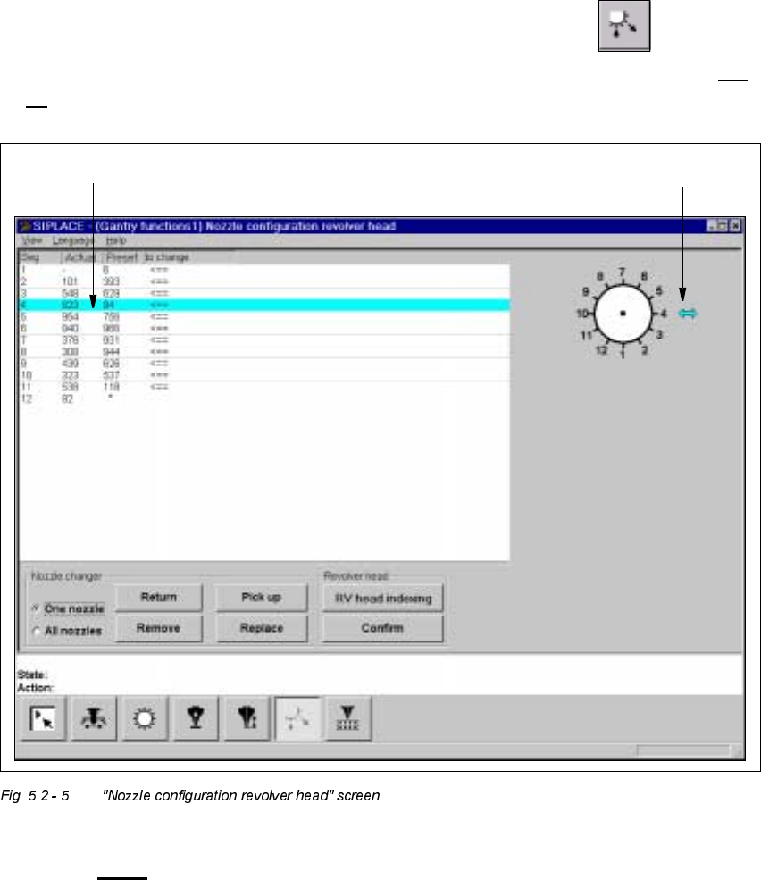
1R]]OHFRQILJXUDWLRQUHY ROY H UKHDGVFUHHQ
Å In the current screen for the single functions for Gantry x, click the symbol .
The user interface is switched to the "Nozzle configuration revolver head" screen (see Fig. 5.2
- 6).
.H\WR)LJ
(1) The entry for the segment currently located in the changeover position is highlighted in
light blue.
(2) The arrow points to the number of the segment which is in the changeover position.
1 2
User’s Manual SIPLACE HS-50 5 Single Functions
Software Version SR.501.xx Edition 01/99 5.2 Single functions, Gantry
163
)XQFWLRQV
The "Nozzle configuration revolver head" screen provides functions which allow you to change
the nozzle configuration and to then confirm that this change has been made. The required
function is carried out by clicking on the appropriate button.
NOTE
The functions "Return", "Pick up", "Remove" and "Replace" can only be carried out if a noz-
zle changer is installed and configured in the machine options.
6HWWLQJV
2QHQR]]OH
If this radio button is activated, the functions "Return", "Pick up", "Remove", and "Replace" can
only be carried out for one selected nozzle. When you call one of these functions a dialog box
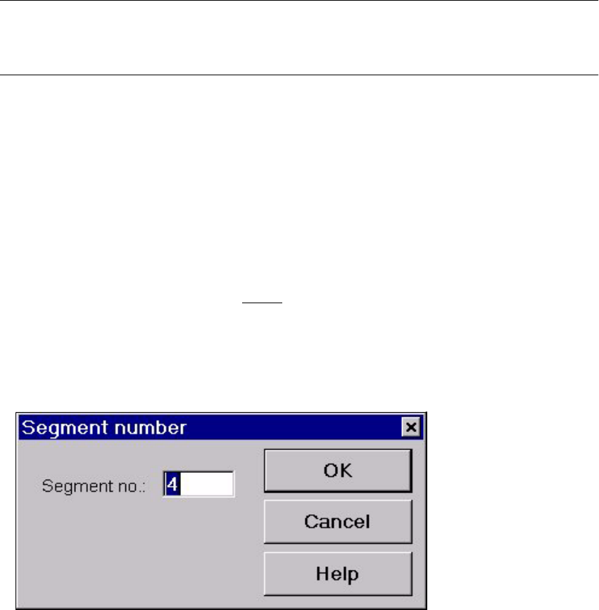
appears. You can enter the number of the segment with the required nozzle.
By default the box already contains the number of the segment currently in the changeover
position (marked by an arrow, see Fig. 5.2 - 5
).
Å Activate the 2QHQ R]]OHradio button.
Å Click the button for the required function.
The dialog box shown below is then displayed.
Å In the entry field, enter the number of the required segment, and confirm with 2.. The func-
tion is then carried out for the selected nozzle.