00191369-01.pdf - 第186页
6 Vision functions User Manual HS-50 6.1 The vision systems on the placem ent system Software-Version 5.01 Edition 01/99 184 4 ICO S 2 ICOS 1 GEM MC X4sv X3sv X2sv X1sv S-COM 1 S-COM 2 AUX VGA HS3L X4su X3su X6su X7su …
User Manual HS-50 6 Vision functions
Software-Version 5.01Edition 01/99 6.1 The vision systems on the placement system
183
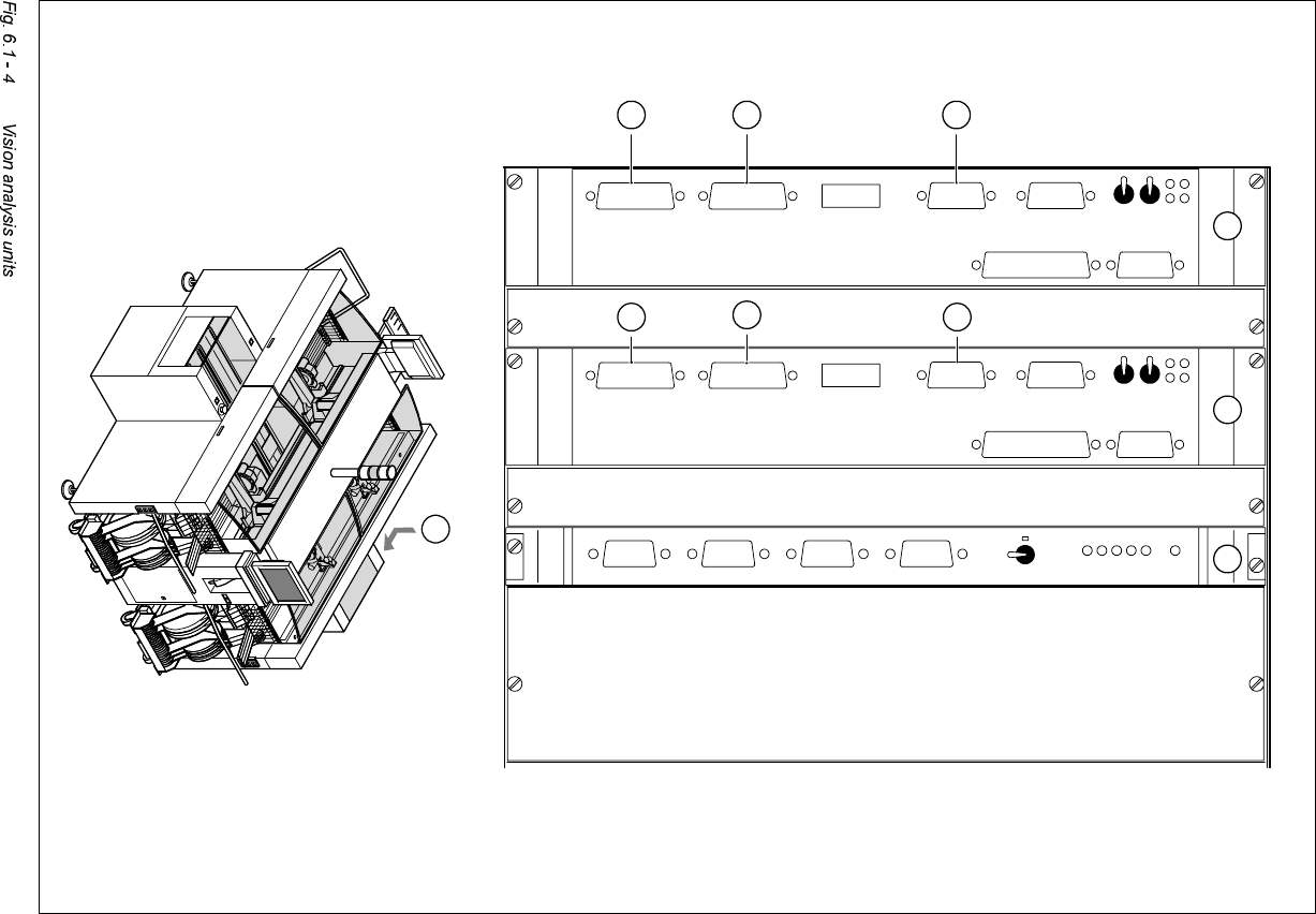
9L VLRQDQDO\VLVXQLWV
The two vision analysis units (see items 1 and 2 in Fig. 6.1 - 4) are plugged into the placement
system’s control unit.
They process and analyze electrical signals from the component and PCB camera systems. Cor-
rection values are calculated from any deviations from setpoint. These values are then used for
recalculating the placement positions and angle of rotation for placement.
The vision analysis units also perform a component identification process. The precise component
pick-up position, which is particularly important for small components, is also determined in the
vision analysis units.
6 Vision functions User Manual HS-50
6.1 The vision systems on the placement system Software-Version 5.01 Edition 01/99
184
4
ICOS 2ICOS 1GEMMC
X4svX3svX2svX1sv
S-COM 1S-COM 2
AUX
VGA
HS3L
X4su
X3su
X6suX7su
X8su
X5suX9su
Abort
Reset
Reset
Abort
X9st X5st X8st
X7st X6st
X3st X4st
HS3L
VGA
AUX
S-COM 2
S-COM 1
Kamera 2/4 Kamera 1/3
Kamera 2/4 Kamera 1/3
1 2 3
9
5
6
10
7
8
User Manual HS-50 6 Vision functions
Software-Version 5.01Edition 01/99 6.2 PCB vision system
185
.H\WR)LJ
(1) MVS 340 vision analysis unit, gantries 1 and 4
(2) MVS 340 vision analysis unit, gantries 2 and 3
(3) Video multiplexer
(4) Position of the control unit
(5) X6st: Component and PCB camera, gantry 1
(6) X7st: Component and PCB camera, gantry 2
(7) X6su: Component and PCB camera, gantry 3
(8) X7su: Component and PCB camera, gantry 4
(9) X5st: Image output (VGA) for plug X3sv (video multiplexer)
(10) X5su: Image output (VGA) for plug X4sv (video multiplexer)
The electronic image signals from components, PCB fiducials and feeder module fiducials can be
transferred from the vision analysis units via the video multiplexer to the two station monitors,
where they are used for measuring and testing purposes.
3&%YLVLRQV\VWHP
The PCB vision system records the precise position of the PCB by measuring fiducials, and cal-
culates the offset in the x and y directions, the angle of rotation relative to the PCB transport di-
rection and the shear acting on the PCB. Reject fiducials (ink spots) are also recorded and
analyzed by the PCB vision system.
6\VWHPGHVFULSWLRQ
The PCB vision system for detecting the position of PCBs consists of the optical PCB position de-
tection system and the vision analysis unit
2SWLFDO3&%SRVLWLRQGHWHFWLRQV\VWHP
Each gantry has a separate PCB position detection system (see Fig. 6.1 - 3 on page 6 - 182).
9LVLRQDQDO\VLVXQLW
The control unit of each placement system contains two analysis units for detecting the position
of PCBs and components (see Fig. 6.1 - 4 on page 6 - 184).
A CCD camera (SONY XC75) with integral mapping and illumination lens forms the optical PCB
position detection system. The field of view of the PCB module is 5.7 mm x 5.7 mm. The size and