00191369-01.pdf - 第34页
1 Introduction User Manual HS-50 1.11 Overview of the modules - controls Software Version 5.01 01/99 Issue 32 2YHUY LHZ RIWKHPRGXOHVFRQWUROV &RQWUROV 1. Operati ng panel, left 7. Comp onent co…
User Manual HS-50 1 Introduction
Software Version 5.01 01/99 Issue 1.10 Setting up the placement system
31
6HWWLQJXSWKHSODFHPHQWV\VWHP
Å Raise the placement system using the fork-lift truck and adjust the feet until there is a gap
of 830 mm (952.5 mm SMEMA height) between the top edge of the PCB conveyors and
the bottom edge of the feet.
Å Leave a gap of 1 to 3 mm between the PCB conveyors of the placement system.
Å Use a cord pulled tight to ensure that all the placement systems are exactly in line with one
another.
Å Adjust each placement system using a spirit level with an accuracy of 0.02 mm/m.
Å Lock the feet in position.
Å Check the placement system again using the spirit level and correct the settings, if neces-
sary.
CAUTION
Make sure that you remove all the shipping braces from the placement system.
Å Fit any components that were dismantled for dispatch.
Å Connect all the electrical and pneumatic lines.
RISK OF DEATH
The electrical connection work MUST be carried out only by appropriately trained and
certified personnel.
1 Introduction User Manual HS-50
1.11 Overview of the modules - controls Software Version 5.01 01/99 Issue
32
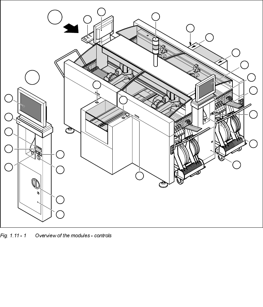
2YHUY LHZRIWKHPRGXOHVFRQWUROV
&RQWUROV
1. Operating panel, left 7. Component counter
2. Main switch 8. LCD screen
3. Key switch 9. Keyboard with trackball
4. Stop button (black) 10.Operating panel, right
5. Start button (white) 11.Emergency stop button
6. Component barcode scanner 12. Indicator lamps
4
5
11
5
11
A
A
10
6
9
8
5
12
8
9
5
5
2
4
3
1
8
9
6
7
5

User Manual HS-50 1 Introduction
Software Version 5.01 01/99 Issue 1.11 Overview of the modules - controls
33
'HVFULSWLRQ
All the controls can be reached by a 1.60 m tall person.
0DLQVZLWFK
The main switch is used to switch the power supply to the placement system on and off.
RISK OF DEATH
Some parts inside the placement system carry potentially lethal voltages - even when
switched off at the main switch.
.H\VZLWFK
In normal mode, the key switch is set to "0". The key should be removed and kept in a safe
place. It must only be turned to position "I" (set-up mode) by authorized personnel, and then
only for certain maintenance and servicing work.
6WRSEXWWRQ
This button is used to stop the placement system.
6WDUWEXWWRQ
This button starts the placement system after it has been switched on or after faults have been
eliminated.
(PHUJHQF\VWRSEXWWRQ
The emergency stop button latches in the ON position when pressed. The power supply to the
gantry axes, the components change-over tables, conveyors, and used tape cutters is inter-
rupted and the voltage supplied to the star axes of the placement heads is reduced. Turn the
button to release it.
&RPSRQHQWFRXQWHU
The component counter displays the number of components processed.
/&'VFUHHQ
There is a flat LCD screen with a touch-sensitive surface (touch-screen) on either side of the
placement system. The screen resolution is 1024 x 768 pixels.