00191369-01.pdf - 第288页
6 Vision functions User Manual HS-50 6.6 Test Component Software-Version 5.01 Edition 01/99 286 In order to d eterm ine the ang le, se lect t he integr ation direc tion t owards eithe r the X o r Y axi s of the compon en…
User Manual HS-50 6 Vision functions
Software-Version 5.01Edition 01/99 6.6 Test Component
285
– TWIN method (Two Windows)
Two windows are selected. This method is particularly suitable for rapid analysis, for PLCCs,
for example. However, this requires the structures to be investigated to lie in the center of the
window. If this is not the case, select just one window (SWIN method).
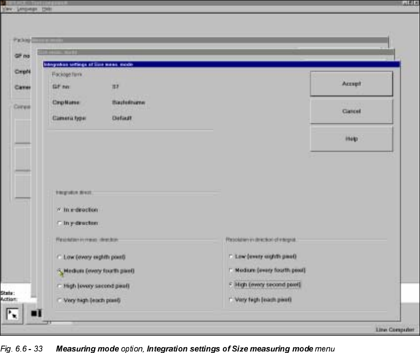
,QWHJUDWLRQVHWWLQJV
If you click on the 'Integration settings' field, the ,QWHJUDWLRQVHWWLQJVRI6L]HPHDVXULQJPRGH
menu will appear on screen.
This menu is used to select the
– integration direction,
– the resolution in the measuring direction and
– the resolution in the integration direction.
,QWHJUDWLRQGL UHF WL RQ
6 Vision functions User Manual HS-50
6.6 Test Component Software-Version 5.01 Edition 01/99
286
In order to determine the angle, select the integration direction towards either the X or Y axis of
the component. We recommend that you select the longer edge.
5HVROXWLRQLQWKHPHDVXULQJGLUHFWLRQ
Select this resolution in order to optimize the measuring times at the revolver head.
5HVROXWLRQLQWKHLQWHJUDWLRQGLUHFWLRQ
Select this resolution in order to optimize the measuring times at the revolver head.
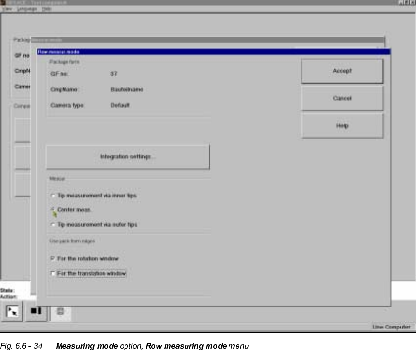
5RZ0HDVXULQJPRGH
Click on the ‘Setting’ field in the 5RZPHDVXULQJPRGH menu to call up the following menu:
This menu is used to
– specify the lead measuring method.
– use the package form edges for the rotation windows and/or translation windows.
User Manual HS-50 6 Vision functions
Software-Version 5.01Edition 01/99 6.6 Test Component
287
0HDVXUHPHQW
If the inner lead tips are mapped better than the outer tips, for example, if a shiny lead is bent up-
wards slightly, you can select one of the following options:
– measuring the tips via the inner tips of the leads, for bases, for example
– center of the lead, center measurement, for PLCC, SOJ, for example
– measuring the tips via the outer tips of the leads, for QFP, SOT, SO, for example
8VHSDFNDJHIRUPHGJHV
– IRUURWDWLRQZLQGRZV
The package form edges can be used to optimally position the rotation windows. However, to
do this, the package form edge must be visible and it must not contain a row of leads.
– IRUWUDQVODWLRQZLQGRZV
The package form edges can be used to optimally position the translation windows. However,
to do this, the package form edge must be visible and it must not contain a row of leads.
,QWHJUDWLRQVHWWLQJV
Once you have clicked on the ‘Integration settings’ field, the 5RZPHDVXULQJPRGHLQWHJUDWLRQ
VHWWLQJV menu will appear on screen.