00191369-01.pdf - 第283页
User Manual HS-50 6 Vision functions Software-Version 5.01Edition 01/99 6.6 Test Component 281 ,QIRUPDWL RQRQ0HDVXUHPHQW0HW KRGV As far as con ventiona l compo nents with lead c onnectio ns are conce rned, co…
6 Vision functions User Manual HS-50
6.6 Test Component Software-Version 5.01 Edition 01/99
280
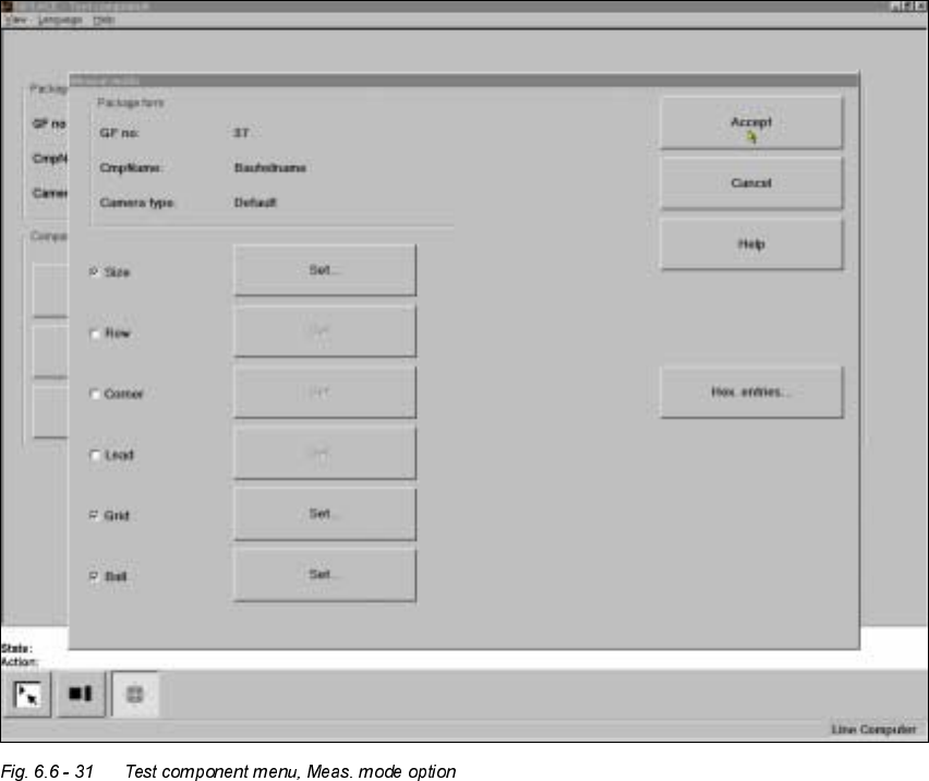
0HDVXULQJPRGHPHQX
Click on the ’Measuringmode’ field to call up the 0HDVXULQJPRGH menu.
– In the left column of the box, the desired measuring method can be activated or deactivated
by clicking with the mouse. A cross indicates that you have activated the measuring method.
The ‘Setting' field for calling up the sub-menu changes from grey to black.
Use the ‘Hex input’ field to call up the ‘Measuring mode 2’ input menu for directly entering hex
values. Please follow the instructions on page 6 - 279.
Å Select ‘Accept’ to close the ‘Measuring mode’ menu. The modified measuring conditions will
be entered into the package form file on the station computer.
Å Select ‘Abort’ to interrupt the operation without transferring the data and to return to the ‘Test
component’ menu.

User Manual HS-50 6 Vision functions
Software-Version 5.01Edition 01/99 6.6 Test Component
281
,QIRUPDWLRQRQ0HDVXUHPHQW0HWKRGV
As far as conventional components with lead connections are concerned, component centering is
essentially based on four measurement methods used to determine the position (x and y coordi-
nates,
Φ
= skew) of the component and the lead parameters:
– Size-driven mode
– Row-driven mode
– Corner-driven mode
– Lead-driven mode
For BGAs (B
all Grid Arrays) and flip-chips new algorithms have been implemented in order to de-
termine the position (x and y coordinates,
Φ
= skew) of the component and the ball parameters
(see Section 6.6.4.4 on page 6 - 257 ):
– Grid-driven mode
– Ball-driven mode
In accordance with your specifications any measurement method can be omitted from this se-
quence. However, it is not possible to change the way this sequence runs.
Definition of the measuring methods
– 6L]HGULYHQ
This measurement method has been especially developed for small components. On the basis
of the information on dimension parameters the position and rotation of small components is
determined rapidly and reliably.
7KLVPHWKRGLVYHU\UHVLVWDQWWRXQZDQWHGLQWUXVLYHHOHPHQWVVXFKDVLQNPDUNLQJV
The size-driven mode also employs profiling. You can have the profile formed along either the
width RU the length of the component. You should make your choice within the options field.
The default selection is for profiling along the longer side.
– 5RZGU LYH Q
This measurement method is based on information from one row of leads.
7KLVPHWKRGLVYHU\IDVWDQGVXSSOLHVDSSUR[LPDWHYDOXHVIRUWKHFRRUGLQDWHVDQGURWDWLRQDO
DQJOHRIWKHFRPSRQHQW
– &RUQHUGULYHQ&RPSRQHQWLQVSHFWLRQ
The measurement results provide precise information on the coordinates and rotation of the
component, the number of leads, the pitch and the row offset.
7KLVPHWKRGLVQRWVHQVLWLYHWRIOXFWXDWLRQVLQWKHOHDGGLPHQVLRQV
– /HDGGULYHQ/HDGVLQVSHFWLRQ
This method is used to obtain information from an inspection of every single lead.
6 Vision functions User Manual HS-50
6.6 Test Component Software-Version 5.01 Edition 01/99
282
The following combinations of measurement methods are used:
– Size-driven — corner-driven — lead-driven (see table in Section 6.6.4.15) or
– Row-driven — corner-driven — lead-driven (see table in Section 6.6.4.15)
– *ULGGULYHQFRPSRQHQWLQVSHFWLRQZLWKWKH)
RU) PDFKLQHV
The measurement results will provide information on the approximate coordinates and approx-
imate rotation of the component. In addition, you will be informed of the quality of measure-
ment.
– The measurement results will provide precise information on the approximate coordinates and
approximate rotation of the component. In addition, you will be informed of the maximum ball
offset and the quality of measurement.
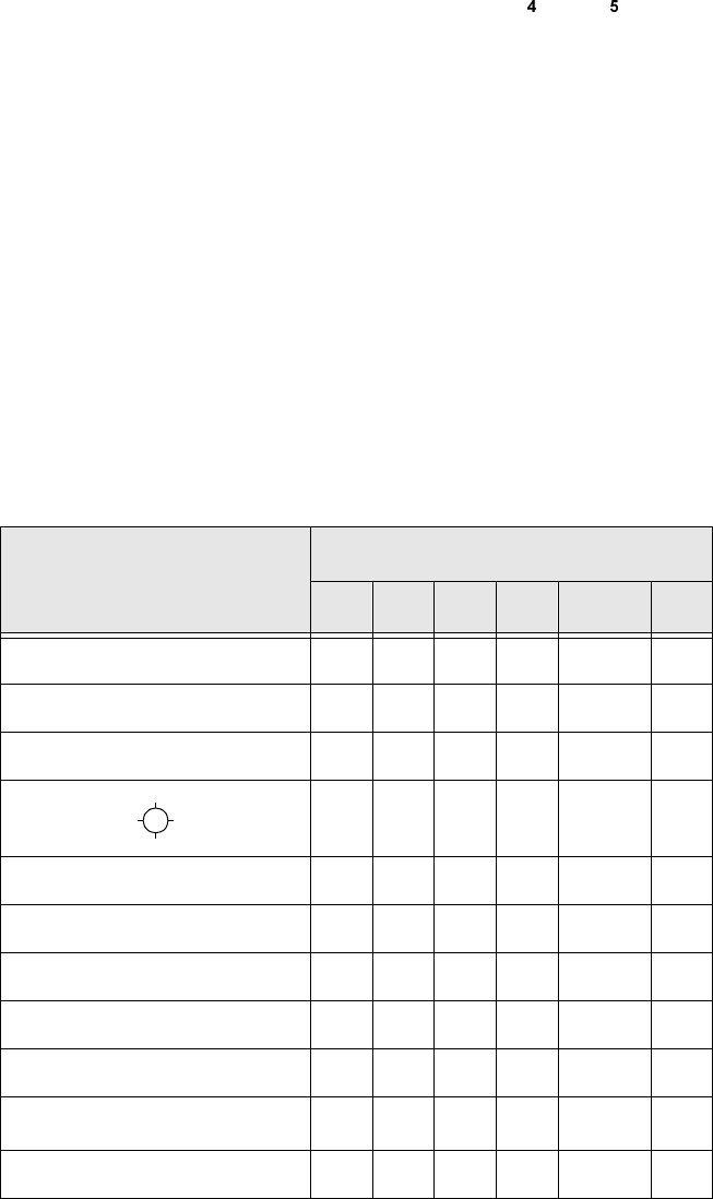
5HFRPPHQGDWLRQVUHJDUGLQJWKH2SWLPXP6HTXHQFHRI0HDVXUHPHQW0HWKRGV
The following table contains our recommendations for the optimum sequence of measurement
methods for particular components. The following abbreviations are used:
B = ball-driven C = corner-driven G = grid-driven
L = lead-driven R = row-driven S = size-driven
&RPSRQHQW
0HDVXUHPHQWVHTXHQFH
6 5 * & / %
MELF S L
CHIP S L
SOT S C L
SL
SOJC6 S C
SOJC14 R C
LCC R C L
PLCC R C L
QFP R C L
TAB R C
L
*)
BGA, flip-chip S G B