00191369-01.pdf - 第199页
User Manual HS-50 6 Vision functions Software-Version 5.01 Edition 01/99 6.3 Component Vision System 197 cess y ield infor matio n on positi onal d eviat ions, lead condi tion and co mponen t identi ficat ion. The HALE p…

6 Vision functions User Manual HS-50
6.3 Component Vision System Software-Version 5.01 Edition 01/99
196
Each 12x revolver placement head is equipped with its own component position recognition sys-
tem in star station 7 (see Fig. 6.1 - 2 on page 6 - 181). Each machine is equipped with an analysis
unit for PCB and component position recognition which is located in the control unit
(see Fig. 6.1 - 4 on page 6 - 184).
The optical component position recognition system (camera) consists of an LED lighting system,
deflection mirror, imaging lens, and CCD chip which acts like the retina in a human eye. LEDs ar-
ranged in three rows illuminate the component being tested, and the reflected light is directed
through a focusing lens onto the surface of the CCD chip. Using the HALE process (High Accuracy
Lead Extraction), the image is digitally processed to determine the parameters for position, skew,
and lead condition.
The vision analysis unit (MVS) has already been described in Section 6.1.3 on page 6 - 183 since
it performs the two functions of PCB and component analysis.
7HFKQLFDO'DWD
Camera type: SONY XC75
Number of pixels: 484 x 484
Field of view: 24 mm x 24 mm
Method of illumination: Reflected light process (red light), 3 LED levels
Image processing: HALE gray scale process (H
igh Accuracy Lead Extraction)
Screen: RGB monitor (VGA mode) 640 x 484 pixels
Component sizes: 0.5 mm x 0.5 mm to 18.7 mm x 18.7 mm
Range of recognizable components : TSOP, LCC, PLCC, QFP, SO series through SO28
basically all components with J and
gull-wing leads,
µ
BGAs
Minimum lead pitch: 0.3 mm
Minimum ball diameter with
µ
BGAs: 250 µm
'HVFULSWLRQRI)XQFWLRQ
One segment of the 12x placement head picks up a component at star station 1. As the star ad-
vances, additional components are picked up. Once a componentz reaches star station 7 where
the component vision system is located, LED lights, as described earlier, illuminate the component
so that the CCD sensor can process the image. The lens will allow components with a height up
to 5 mm to be sharply focused and recognized by the camera’s CCD chip.
The digitally processed image is then transmitted to the vision analysis unit. Using the HALE pro-
cess, the analysis unit compares the image of the component with a synthetic model previously
generated in the GF editor (the package form editor). The parameters obtained through this pro-
User Manual HS-50 6 Vision functions
Software-Version 5.01Edition 01/99 6.3 Component Vision System
197
cess yield information on positional deviations, lead condition and component identification. The
HALE process has proved to be highly resistant to interference factors such as unwanted reflec-
tions, diffused light influences , etc. and it is faster and more accurate than the matching method.
Once measurement has been completed, the star advances to station 9 where the segment ro-
tates the component into the correct orientation for placement. Finally, in star station 1, the com-
ponent is placed in its correct position on the board.
&ULWHULDIRU5HFRJQLWLRQRI&RPSRQHQWV
6KDSHRIWKH&RPSRQHQWV
Optical component centering allows both regular and irregular components to be centered. The
maximum number of leads, horizontally and vertically, is 99 in each case.
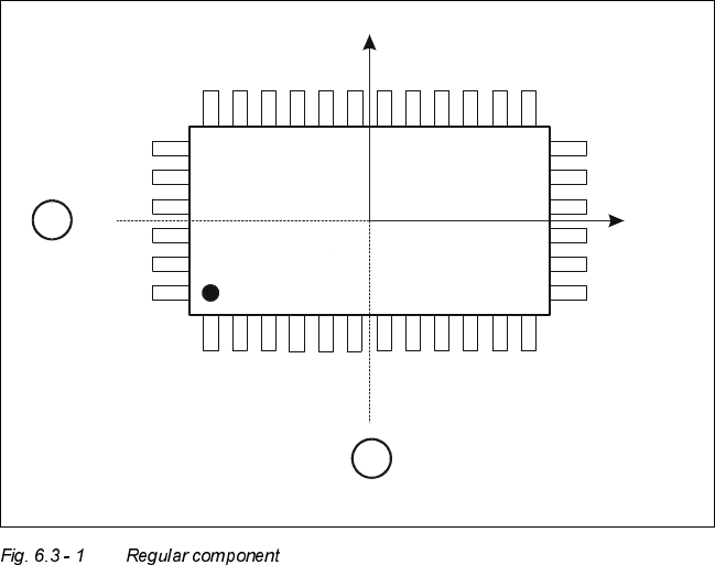
&ULWHULDIRUUHJXODUFRPSRQHQWV
Definition:
A component is deemed to be regular when it satisfies the following four conditions:
– rectangular package shapes (special case: square shape)
– only one lead type per side
– only one lead group per side
– opposite lead groups located symmetrically with respect to the two main axes
(x and y axes).
Y
X
Pin 1
1
1
6 Vision functions User Manual HS-50
6.3 Component Vision System Software-Version 5.01 Edition 01/99
198
.H\WR)LJ
(1) Axis of symmetry
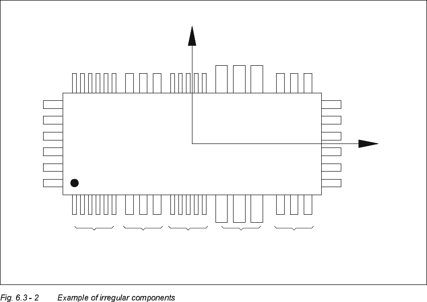
&ULWHULDIRULUUHJXODUFRPSRQHQWV
Definition:
A component is deemed to be irregular when it does not satisfy the conditions for regular compo-
nents.
Additional conditions for centering with the component vision system:
– In any one row up to 3 different lead types are permitted.
– In any one row up to 15 groups are permitted.
3LWFKGHYLDWLRQ
The pitch deviation (which is the distance from the center of one lead to the center of the next) can
be edited separately for each component in the GF editor. If this value is exceeded during the vi-
sion inspection, the component will not be centered and therefore not placed.
X
Pin 1
Y
X
Pin 1
Type 1
Group 1
Type 2
Group 1
Type 1
Group 2
Type 3
Group 1
Type 2
Group 2