00191369-01.pdf - 第72页
2 Operational Safety User Manual HS-50 2.2 Safety equipment Software-Version 5.01 Edition 01/99 70 *XDUGVRQWKHFRPSRQHQWW DEOHORFDWLRQV DANGER All loc ations mu st be equi pped wi th feeder modules in order t…
User Manual HS-50 2 Operational Safety
Software-Version 5.01Edition 01/99 2.2 Safety equipment
69
PCC*)
y axis
x axis
star axis
dp axis
z axis
PCB conveyor
PCB clamping
Width adjustment
PCB stopper
Lifting table
Used tape cutter
Active
Yes
Voltage
200V
200V
100V
30V
30V
Active
Yes
Yes
Yes
Yes
Yes
Yes
PCC*)
y axis
x axis
star axis
dp axis
z axis
PCB conveyor
PCB clamping
Width adjustment
PCB stopper
Lifting table
Used tape cutter
Active
No
Voltage
0V
0V
6V
30V
30V
Active
Yes
No
Yes
No
No
No
PCC*)
y axis
x axis
star axis
dp axis
z axis
PCB conveyor
PCB clamping
Width adjustment
PCB stopper
Lifting table
Used tape cutter
Active
No
Voltage
0V
0V
6V
30V
30V
Active
No
No
No
No
No
No
*) PCC Protective contactor combination
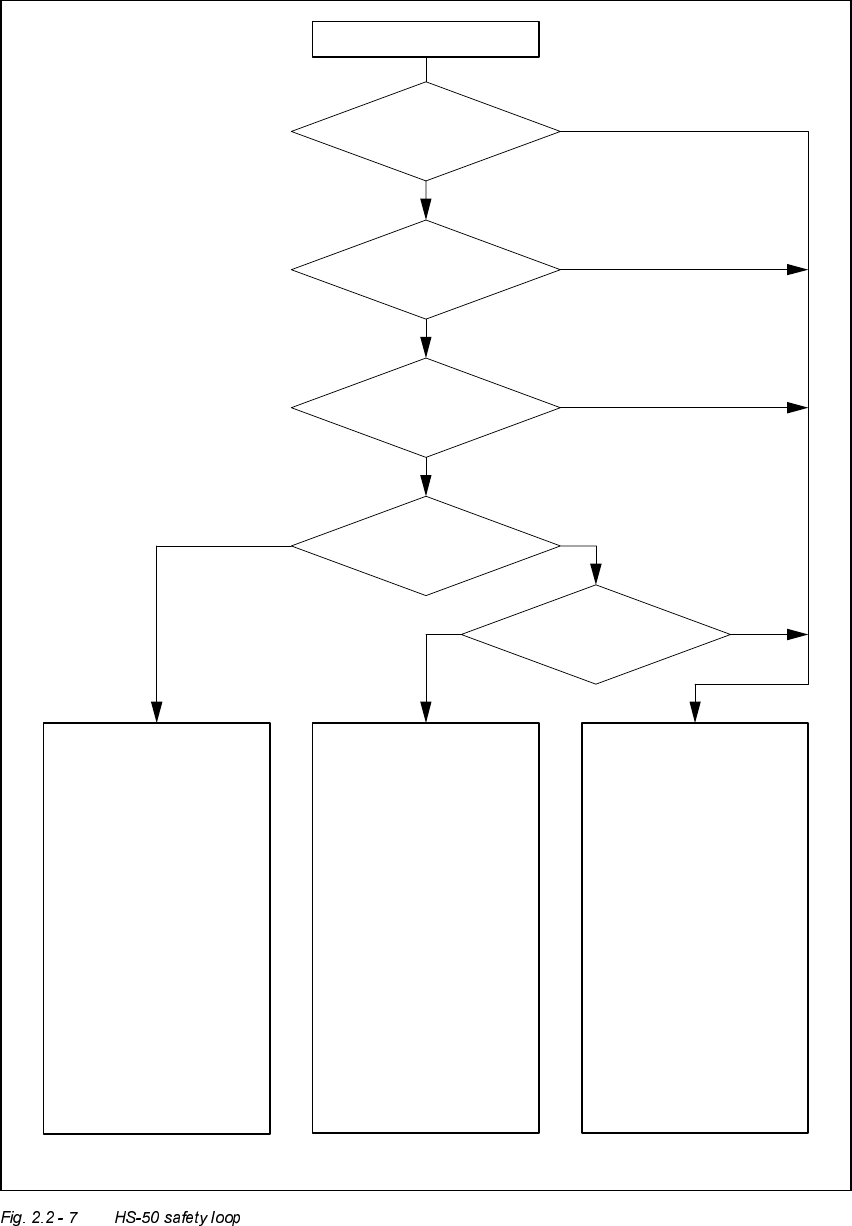
Startbutton pressed
Compressed air
min. 5.0 bar?
Emerg.stop button
pressed?
Component table safety
circuit interrupted?
Protective cover open?
Key switch
closed (position “I”)?
Yes No
Yes
No
No
Yes
Yes
Yes
No
No
2 Operational Safety User Manual HS-50
2.2 Safety equipment Software-Version 5.01 Edition 01/99
70
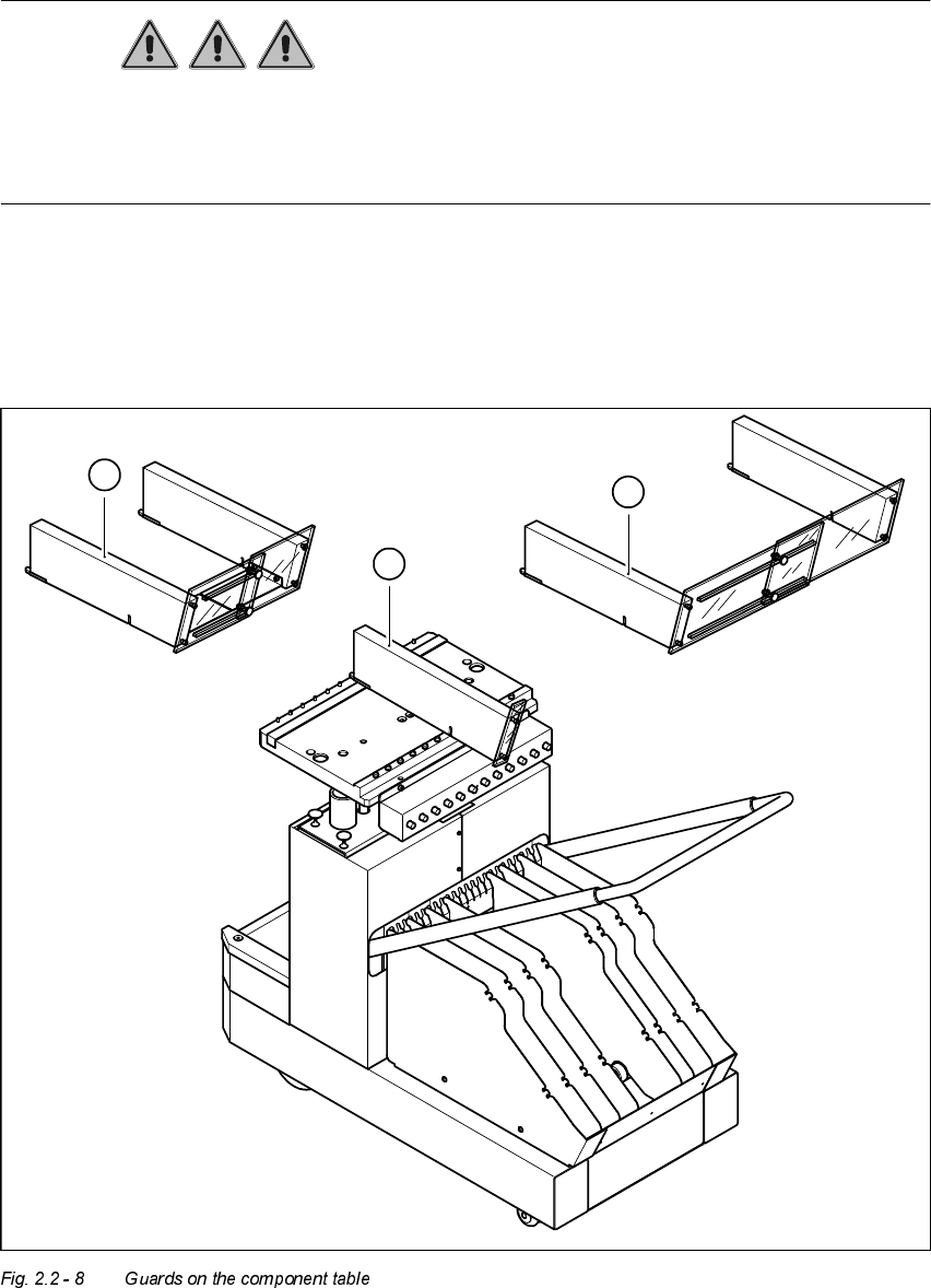
*XDUGVRQWKHFRPSRQHQWWDEOHORFDWLRQV
DANGER
All locations must be equipped with feeder modules in order to guarantee operational safety. If
there are not enough feeder modules available, a guard (dummy feeder) must be used in place
of the modules.
The following variants can be used:
Item no. 00116820-01 SIPLACE guard for 1 location
Item no. 00116821-01 SIPLACE guard for 6 - 10 locations
Item no. 00116822-01 SIPLACE guard for 11 - 20 locations
1
3
2
User Manual HS-50 2 Operational Safety
Software-Version 5.01Edition 01/99 2.3 Residual voltages in the servo unit and discharge times when the placement system is switched
off
71
5HV LGXDOY ROWDJHVLQWKHV HUY RXQLWDQGGLVFKDUJH
WLPHVZKHQWKHSODF HPHQWV\V WHPLVVZLWFKHGRII
If the emergency stop mushroom-head push-button is pressed or the placement system is swit-
ched off, the 200 V link voltage for the gantry axes and 100 V link voltage for the star axes are
discharged to harmless residual voltages in a very short time.
The voltages can be tapped at test sockets X1 - X4 on the voltage measuring unit in the servo
unit.
DANGER
The placement system is supplied with 3 x 204 V (US-Version), 3 x 400 v or 3 x 460 V ± 10%, 50/
60 Hz main power voltage. This means that some parts of the system carry potentially lethal volt-
ages - even when switched off at the main switch. Incorrect handling of the placement system
can therefore result in death or severe injury or considerable damage to equipment.
Å Always follow the applicable accident prevention and DIN regulations (particularly DIN EN
60 204, part 1).
Å The cover over the servo unit must only be opened by qualified and trained personnel.
1. Guard for 1 location 2. Guard for 6 - 10 locations
3. Guard for 11 - 20 locations