00191369-01.pdf - 第383页
User Manual HS-50 11 Station extensions / options Software Vers ion 5.0101/99 Issue 11.1 HS-50 nozzle c hanger 381 0RGHRIRSHUDWLRQ The nozz les are sea ted in noz zle gar ages and are held i n place by a mo va…
11 Station extensions / options User Manual HS-50
11.1 HS-50 nozzle changer Software Version 5.01 01/99 Issue
380
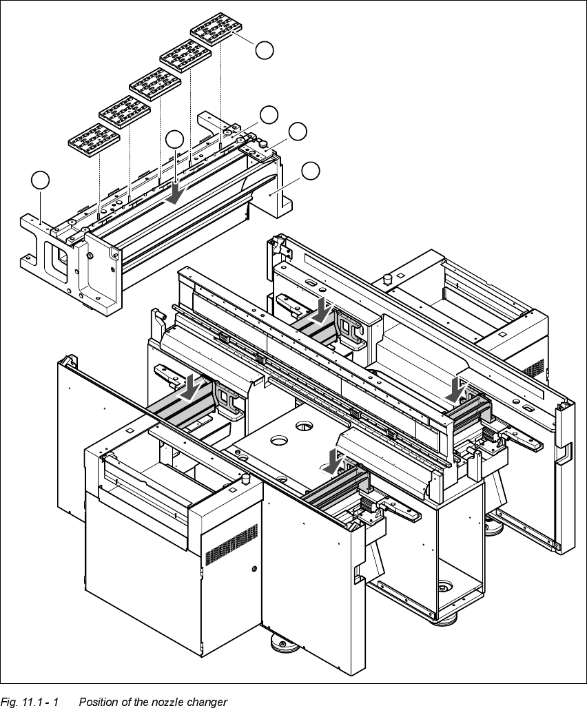
.H\WR)LJ
(1) Used tape guide channel (2) Nozzle discarding device
(3) Nozzle changer (4) Nozzle magazines
(5) Location for optional 2nd nozzle changer
(6) Container for discarded nozzles
1
2
3
4
5
6

User Manual HS-50 11 Station extensions / options
Software Version 5.0101/99 Issue 11.1 HS-50 nozzle changer
381
0RGHRIRSHUDWLRQ
The nozzles are seated in nozzle garages and are held in place by a movable locking plate. The
locking plate can be moved 6 mm by a pneumatic cylinder. All the nozzles are either clamped or
released, depending on the position of the plate. The default position of the locking plate, i.e. if
there is no nozzle change in progress, is "closed".
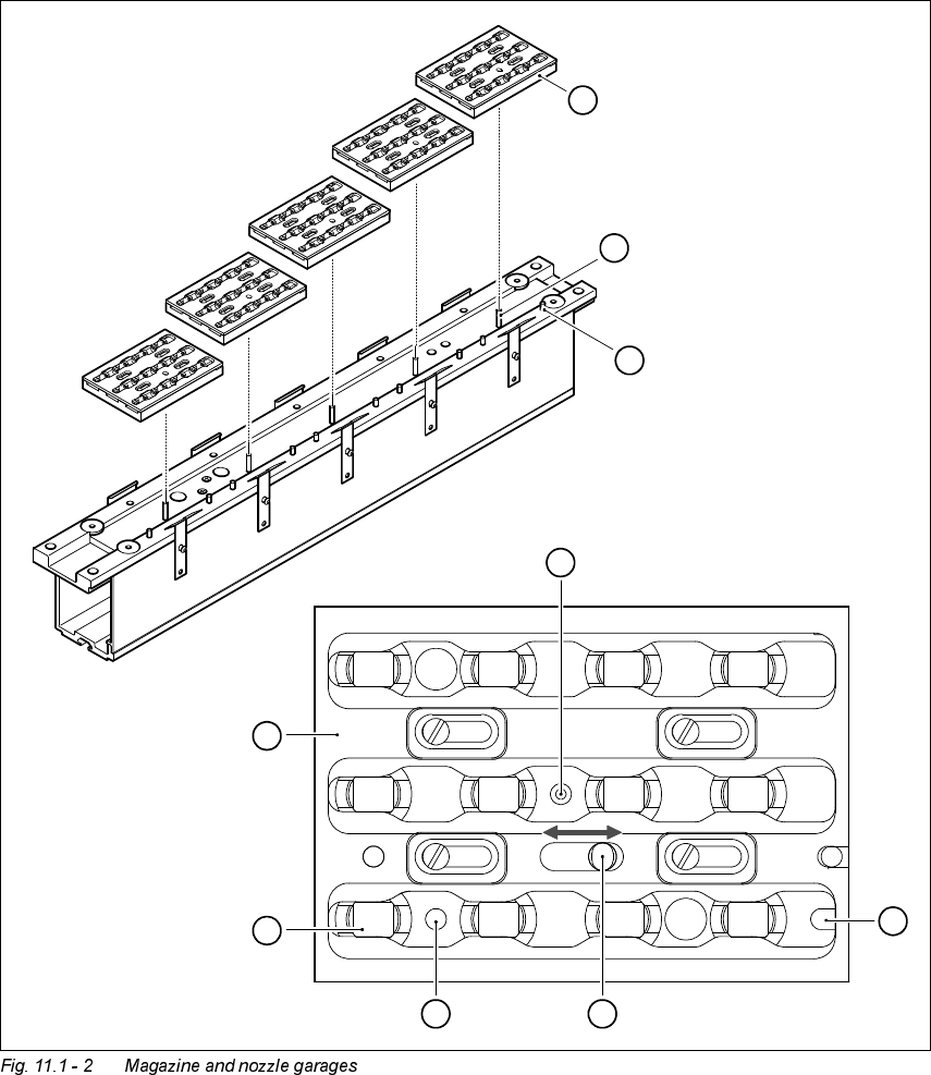
There is a positioning fiducial for position detection on each magazine of the nozzle changer. The
magazine locations are identified by numbers 1 to 5 on the nozzle changer. The nozzle garages
in the magazines are numbered consecutively from 1 to 12 (see Fig. 11.1 - 2).
PLEASE NOTE
Special magazines are available upon request (contact Siemens PL EA 1E for details) and will be
numbered differently.
3LFNLQJXSDQR]]OH
– The revolver head z axis moves down.
– The locking plate (item 3 in Fig. 11.1 - 2) opens and releases the nozzle garages.
– The nozzle is picked up by the sleeve of the revolver head.
– The z axis moves up.
6HWWLQJGRZQDQR]]OH
– The locking plate (item 3 in Fig. 11.1 - 2) opens and releases the nozzle garages.
– The revolver head z axis moves down and sets the nozzle down.
– The locking plate closes.
– The revolver head z axis moves up.
'LVFDUGLQJGHIHFWLYHQR]]OHV
– The revolver head z axis moves down 14 mm towards the discarding device (item 2 in Fig. 11.1
- 1) and thus moves the defective nozzle into the hole in the discarding device.
– The z axis moves up again and the nozzle is stripped from the sleeve by spring wires.
– The nozzle drops into the container of the used tape guide channel (item 6 in Fig. 11.1 - 1).
11 Station extensions / options User Manual HS-50
11.1 HS-50 nozzle changer Software Version 5.01 01/99 Issue
382
.H\WR)LJ
(1) Positioning fiducial
(2) Locking plate
(3) Nozzle garage
(4) Hole for the parallel pin (7) for centering the magazines
(5) Hole for the parallel pin of the slide mechanism
12 3
4
5
6
7
8
91011
12
9
8
6
5
4
7
3
2
1
1
2
3
4
5