00191369-01.pdf - 第235页
User Manual HS-50 6 Vision functions Software-Version 5.01Edition 01/99 6.5 Teach Fiducial 233 Å After se lecting th e step wi dth (by choosi ng a numb er between 1 a nd 6) you can u se the arr ow keys to c hange th e …
6 Vision functions User Manual HS-50
6.5 Teach Fiducial Software-Version 5.01 Edition 01/99
232
Following this
– the test will be shown on the video display as it runs,
– the header will be shown with the option, the fiducial number and the quality factor, and
– in the footer the operator fields and command sequences will be shown and a test started
which determines the fiducial’s quality factor.
Å By pressing the 5HWXUQ key you can repeat the test procedure.
Å You can change the position of the gantry with the arrow keys. By entering the numbers 1 - 6
you can change the step width.
The PCB camera travels into the 4 corners of the search area, and each time, issues a measure-
ment command. For each measurement command, the machine controller is provided with the fi-
ducial quality by the vision analysis unit (MVS). The worst value (which is the worst case) of the
test is displayed on the screen in the header.
The quality value is a figure between 0 (= bad) and 100 (= very good) and should not fall below
the value 40 for the fiducial and the ink dot. If it does, we recommend you choose another fidu-
cial.
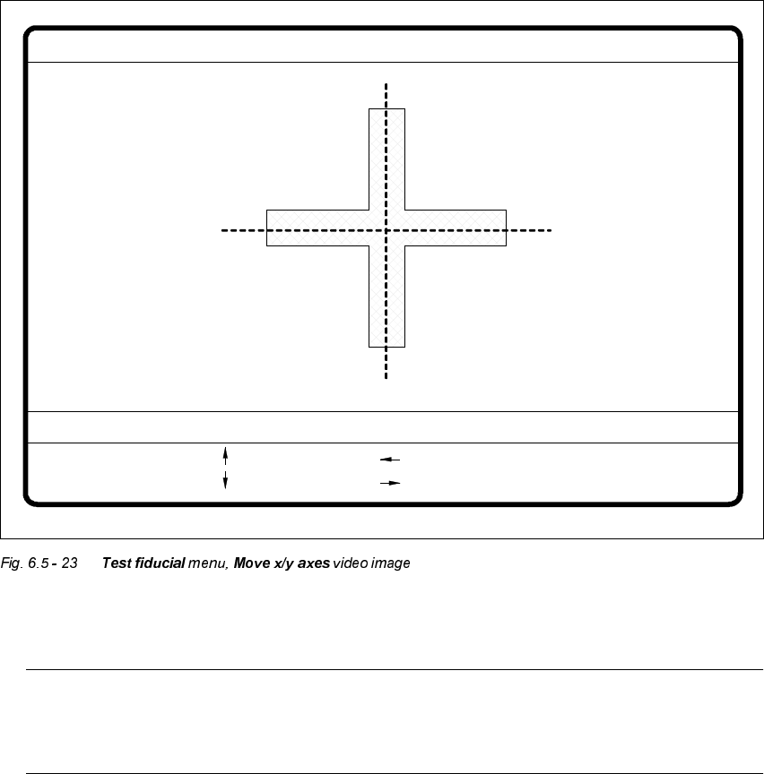
0RYH;<$[HV2SWLRQ
When you select this option from the 7HVWILGXFLDO menu, the station computer will have the fol-
lowing actions carried out:
– The screen will close the 7HVWILGXFLDO menu and will switch over to the video image. At the
same time the current camera position will be displayed and the operator field option dropped
down.
– If there is the risk of a gantry/head crash, the axis controllers will be blocked.
User Manual HS-50 6 Vision functions
Software-Version 5.01Edition 01/99 6.5 Teach Fiducial
233
Å After selecting the step width (by choosing a number between 1 and 6) you can use the arrow
keys to change the camera position of gantry 1.
NOTE
The default teaching gantry is always Gantry 1. You can, however, select Gantry 2, 3, or 4,
for this by using the 6HOHFWJDQWU\option (see Section 6.5.3.1 on page 6 - 212).
Å With (VF you can quit the option. The 7HVWILGXFLDO menu will be displayed again.
: x axis +
: x axis -
: y axis +
: y axis -
1..6: x/y step
x pos. cam = y pos. cam =
Move x/y axes
x/y step width =

6 Vision functions User Manual HS-50
6.5 Teach Fiducial Software-Version 5.01 Edition 01/99
234
3&% WR3URFHVVLQJ&RQYH\RU2SWLRQ
Click on the 3&%WRSURFHVVLQJFRQYH \RU button and the following actions will be executed:
(1) There is a board on the input conveyor.
– The conveyor belt starts and conveys the board as far as the stopper.
– The board will be clamped.
(2) There is no board on the input conveyor.
– The message appears: ’No PCB on the input conveyor’.
– Insert a board.
– Click on the 3&%WRSURFHVVLQJFRQYH\RU button.
– The conveyor belt starts and conveys the board as far as the stopper.
– The board will be clamped.
NOTE
If there is already a board on the processing conveyor, this function will be blocked. You will
then see a message informing you that there is already a board on the processing conveyor.
NOTE
If a twin conveyor is installed you can use the buttons in the option box ’Conv. selection’ to
select conveyor 1 or conveyor 2.
3&%WR2XWSXW&RQYH\RU2SWLRQ
This function will only be executed when there is a board on the processing conveyor.
NOTE
When you quit the menu, the board will be transported automatically onto the output conveyor.
NOTE
If a twin conveyor is installed, you can use the buttons in the option box ’Conv. selection’ to select
conveyor 1 or conveyor 2.