00191369-01.pdf - 第285页
User Manual HS-50 6 Vision functions Software-Version 5.01Edition 01/99 6.6 Test Component 283 *) L applie s to i rregularly shaped c ompone nts with separate wi ndows µ6L]H¶ P HDVXULQJPRGH Click o n the ‘ …
6 Vision functions User Manual HS-50
6.6 Test Component Software-Version 5.01 Edition 01/99
282
The following combinations of measurement methods are used:
– Size-driven — corner-driven — lead-driven (see table in Section 6.6.4.15) or
– Row-driven — corner-driven — lead-driven (see table in Section 6.6.4.15)
– *ULGGULYHQFRPSRQHQWLQVSHFWLRQZLWKWKH)
RU) PDFKLQHV
The measurement results will provide information on the approximate coordinates and approx-
imate rotation of the component. In addition, you will be informed of the quality of measure-
ment.
– The measurement results will provide precise information on the approximate coordinates and
approximate rotation of the component. In addition, you will be informed of the maximum ball
offset and the quality of measurement.
5HFRPPHQGDWLRQVUHJDUGLQJWKH2SWLPXP6HTXHQFHRI0HDVXUHPHQW0HWKRGV
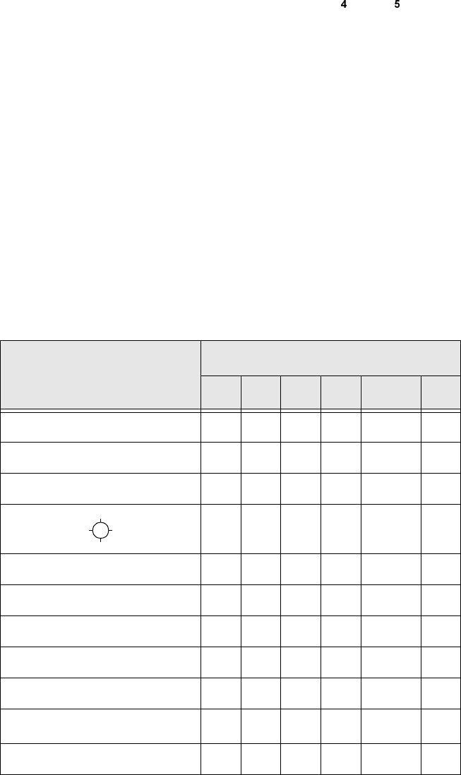
The following table contains our recommendations for the optimum sequence of measurement
methods for particular components. The following abbreviations are used:
B = ball-driven C = corner-driven G = grid-driven
L = lead-driven R = row-driven S = size-driven
&RPSRQHQW
0HDVXUHPHQWVHTXHQFH
6 5 * & / %
MELF S L
CHIP S L
SOT S C L
SL
SOJC6 S C
SOJC14 R C
LCC R C L
PLCC R C L
QFP R C L
TAB R C
L
*)
BGA, flip-chip S G B
User Manual HS-50 6 Vision functions
Software-Version 5.01Edition 01/99 6.6 Test Component
283
*)
L applies to irregularly shaped components with separate windows
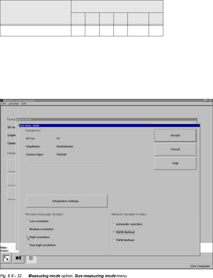
µ6L]H¶PHDVXULQJPRGH
Click on the ‘Setting’ field for the ‘Size’ measuring mode to overlay the 6L]HPHDVXULQJPRGH
menu on the screen.
This menu is used to
– vary the resolution the angle calculation.
– specify the method for the rotation calculation and
Bare dies S
&RPSRQHQW
0HDVXUHPHQWVHTXHQFH
6 5 * & / %
Tab. 6.6.1

6 Vision functions User Manual HS-50
6.6 Test Component Software-Version 5.01 Edition 01/99
284
– vary the integration settings.
5HVROXWLRQIRUWKHDQJOHFDOFXODWLRQ
In this measuring mode, if the component rotation has been calculated incorrectly on account of
ambiguity, you can increase the angular resolution in order to determine the angle of rotation. The
following increments may be used in relation to the resolution in order to determine the angle of
the components:
– Low resolution:
– Medium resolution
Determining the angle every 4° within the angular tolerance
– High resolution
Determining the angle every 2° within the angular tolerance
– Very high resolution
Determining the angle every 1° within the angular tolerance
0HWKRGIRUFDOFXODWLQJWKHURWDWLRQ
Here you must specify the number of rotation windows in order to determine the angle:
– Automatic selection
The system selects the number of windows.
– SWIN method (Single Window)
Selects a single window. This method is suitable for small components and fluctuating dimen-
sions.
$ QJXODUWROHUDQFH
Determining the
angle for the
following
angles
- Angular tolerance
2
- 15° - 33°
0° - 8° - 18°
+Angular tolerance
2
0° - 8°
8° 0°
15° 8°
18°
33°
Tab. 6.6.2