00191369-01.pdf - 第276页
6 Vision functions User Manual HS-50 6.6 Test Component Software-Version 5.01 Edition 01/99 274 3DFNDJH'LPHQVLRQ 2SWLRQ There is potenti al for the occu rrence of an e ffect call ed image r educt ion ma in…

User Manual HS-50 6 Vision functions
Software-Version 5.01Edition 01/99 6.6 Test Component
273
Å You can use the arrow keys to increase or decrease the brightness of the rows of LEDs in the
component camera system which illuminate the component. The brightness can be set within
a range of 256 steps with 255 being the maximum value.
Å Use the spacebar to toggle the step size for changing the brightness from 1 to 10 µm and back.
Å Use the tab key to move between the four illumination levels: steep (top row of LEDs), medium
(second row of LEDs), flat (third row of LEDs) and X plane camera lighting (bottom row of
LEDs). The X plane illumination level is used to optically center flip-chip components on the 6-
nozzle revolver head with the illumination system for flip-chips, bare dies and standard com-
ponents.
Å Press the 5HWXUQ key to execute the individual measurement steps which are included in the
measurement conditions.
Å With (VFyou can quit the option. You will then be returned to the 7HVWFRPSRQHQW menu.
NOTE
Section 6.7.6 from page 6 - 304 contains instructions for selecting the illumination parameters.
6 Vision functions User Manual HS-50
6.6 Test Component Software-Version 5.01 Edition 01/99
274
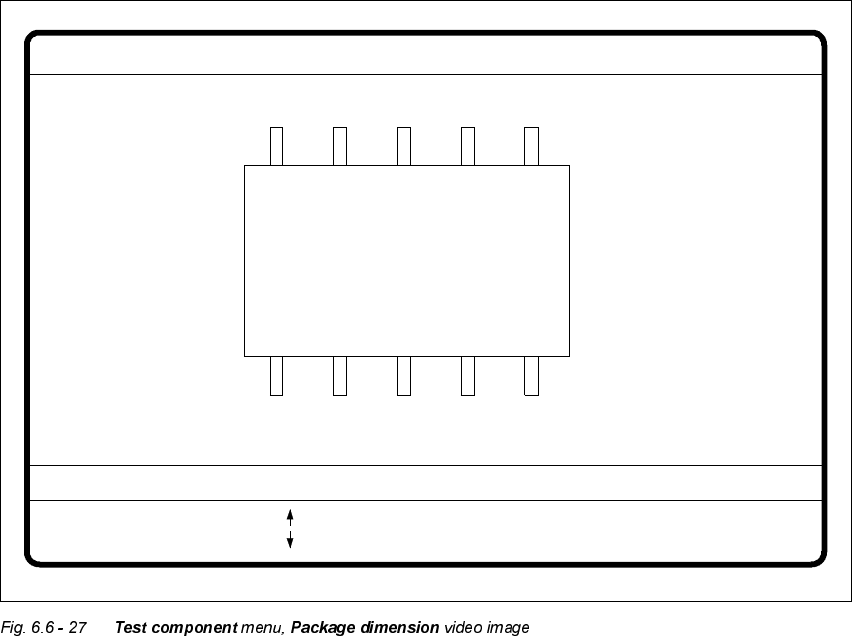
3DFNDJH'LPHQVLRQ2SWLRQ
There is potential for the occurrence of an effect called image reduction mainly with cylindrical
components and with PLCCs. The reduction is caused by the round features of the components
that deflect incident light away from the camera sensor. Typically, the round edges then become
invisible to the camera. To remedy this problem, use the Package Dimension option to change the
optical package width and length to accommodate for the loss.
Å With the arrow keys you can change the length and width of the component. The current geo-
metric data will be displayed.
Å Use the spacebar to select different sides of the component.
Å With the 5HWXUQkey you can trigger the individual measurement steps which are specified in
the measurement conditions.
Å Press (VFto quit the option.
GF No. = 5
: larger
: smaller
RET: Test component
Blank: Pack. side
Pack. side = opt. l.[mm] = ... opt. w.[mm] = ...
Package dimension
User Manual HS-50 6 Vision functions
Software-Version 5.01Edition 01/99 6.6 Test Component
275
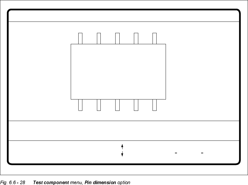
3LQ'LPHQVLRQ2SWLRQ
Use this option to change the optical pin width and length. In addition, the pin contrast can be
changed if imaging reduction results in the pins not being dependably recognized.
Å Use the tabulator key to select the pin model.
Å With the spacebar select the side of the pin.
Å Use the and keys to raise or lower the pin contrast.
Å The arrow keys are used for changing the pin width and length. The component will appear as
a silhouette on the screen together with the updated geometric pin data.
Å With the 5HWXUQkey you can trigger the individual measurement steps which are specified in
the measurement conditions for the specified component.
Press (VFto cancel the option, even if not all measurement steps have been carried out. You will
then be returned to the 7HVWFRPSRQHQW menu.
GF No. = 5Pin dimension
+ : contrast +
opt. l. [mm] = ... opt. w. [mm] = ...
Pin side =
Pin definition = 1..n
RET: Test component
Tab: Pin model
Blank: pin side
Pin contrast =
: larger
: smaller
: contrast