00191369-01.pdf - 第394页
11 Station extensions / options User Manual HS -50 11.3 Dual conveyor Software Version 5.01 01/99 Issue 392 7 HFKQLFDOGDW DIRUWKHGXDOFRQY H\ RU 0DLQWHQDQFH The indiv idual co nveyor belts and t…

User Manual HS-50 11 Station extensions / options
Software Version 5.0101/99 Issue 11.3 Dual conveyor
391
If the placement sequence is interrupted, the conveyor interface will be disabled and the PCBs
currently on the processing belts will be completed.
The conveyor interface is disabled or enabled simultaneously for both transport tracks.
6\QFKURQRXVFRQY H\RUPRGH
'HVFULSWLRQ
In synchronous mode, two PCBs of the same size are moved into the placement position at the
same time. They must be processed as a single cluster.
This enables the top and bottom of a PCB to be processed on a single line. This reduces the time
needed to transport the PCBs, since two PCBs are always transported at the same time.
)XQFWLRQ
PCBs on transport tracks 1 and 2 are moved synchronously (i.e. the conveyor belts are indepen-
dent of one another, but are controlled synchronously) on the conveyor sections. The components
to be placed for transport track 1 and 2 must be organised as a cluster in two circuit images (see
the line computer operating instructions).
If only one transport track (or processing belt) is occupied at the start of the placement sequence,
the circuit image for this conveyor section is identified as "do not place".
&RQWUROOLQJWKHGXDOFRQYH\RUZLWKWKH6LQJOHIXQFWLRQVPHQX
Control of the dual conveyor and the Single functions menu are described in section 5 of these
operating instructions.
$XWRPDWLFZLGWKDGMXVW PHQWRQWKHGXDOFRQYH\RU
PLEASE NOTE
The conveyor setpoint width relates to both conveyor belts. When the command is received, the
conveyor belts are set to the setpoint width one after another.
$XWRPDWLFZLGWKDGMXVWPHQWLVGHDFWLYDWHGZKHQV\QFKURQRXVFRQY H\RULVVHOHFWHG.

11 Station extensions / options User Manual HS-50
11.3 Dual conveyor Software Version 5.01 01/99 Issue
392
7HFKQLFDOGDWDIRUWKHGXDOFRQYH\RU
0DLQWHQDQFH
The individual conveyor belts and the additional lifting table require the same maintenance as the
standard conveyor. Each conveyor belt must be maintained as described in the maintenance in-
structions.
PCB format
50 mm x 50 mm to 368 mm x 216 mm
2" x 2" to 14.5 " x 8.5 "
PCB thickness 0.3 mm to 4.5 mm
Maximum PCB warpage
Up: 4.5 mm - PCB thickness
Down: 0.3 mm + PCB thickness
Clearance on bottom of PCB
Standard: 25 mm
Option: up to 40 mm
PCB conveyor height
830 ± 15 mm (standard)
950 ± 15 mm (option) SMEMA
Type of interface
Siemens (standard)
SMEMA (option)
Free component guide edge 3 mm
PCB changeover time 2.5 s
Fixed transport side Right (standard), left (option)
Components to be placed per conveyor
Synchronous: same or different
Asynchronous: same
PCB width per conveyor
Synchronous: different
Asynchronous: same
Ink spot recognition
Synchronous: not possible
Asynchronous: possible
Automatic width adjustment
Synchronous: not possible
Asynchronous: possible
User Manual HS-50 11 Station extensions / options
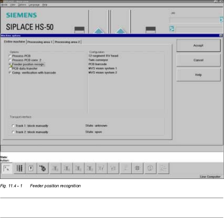
Software Version 5.0101/99 Issue 11.4 Feeder position recognition
393
)HHGHUSRVLWLRQUHFRJQLW LRQ
If the feeder modules are equipped with positioning fiducials, the fiducials can be measured.
If the "Conveyor position detection" function has been selected on the line computer, the function
will also appear in the Machine options. It can then be activated or deactivated at each station.
PLEASE NOTE
The "Feeder position recognition" function is always deactivated when the station is switched on.
If a track has been entered in the cluster data, the PCB camera on the feeder module will approach
the position of the centering fiducial. Any centering fiducial offset determined during the measure-
ment will then be assigned to this track and added to the pick-up position during the pick-up ope-
ration.