00191369-01.pdf - 第185页
User Manual HS-50 6 Vision functions Software-Version 5.01Edition 01/99 6.1 The vision systems on the placement system 183 9L VLRQDQDO\VLVXQLW V The two vis ion anal ysis u nits (see item s 1 an d 2 in Fig. 6 .1 …
6 Vision functions User Manual HS-50
6.1 The vision systems on the placement system Software-Version 5.01 Edition 01/99
182
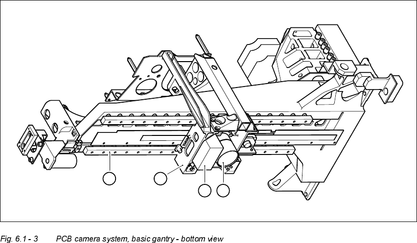
3&%FDPHUDV\VWHPV
.H\WR)LJ
(1) PCB camera - lens and illumination
(2) Camera amplifier
(3) Head mount
(4) Gantry
The PCB camera system (see items 1 and 2 in Fig. 6.1 - 3) essentially consists of the following
components:
– Lens system
– CCD chip
– CCD camera amplifier
– An illumination plane for illuminating PCB fiducials and ink spots
The PCB camera system is fixed to the revolver head mount on the underside of the gantry. As
standard, it can center PCBs from 50 mm x 50 mm up to 368 mm x 460 mm (2" x 2" to 14.5" x 18")
in size, with the thickness ranging from 0.5 mm to 4.5 mm.
1
2
4
3
User Manual HS-50 6 Vision functions
Software-Version 5.01Edition 01/99 6.1 The vision systems on the placement system
183
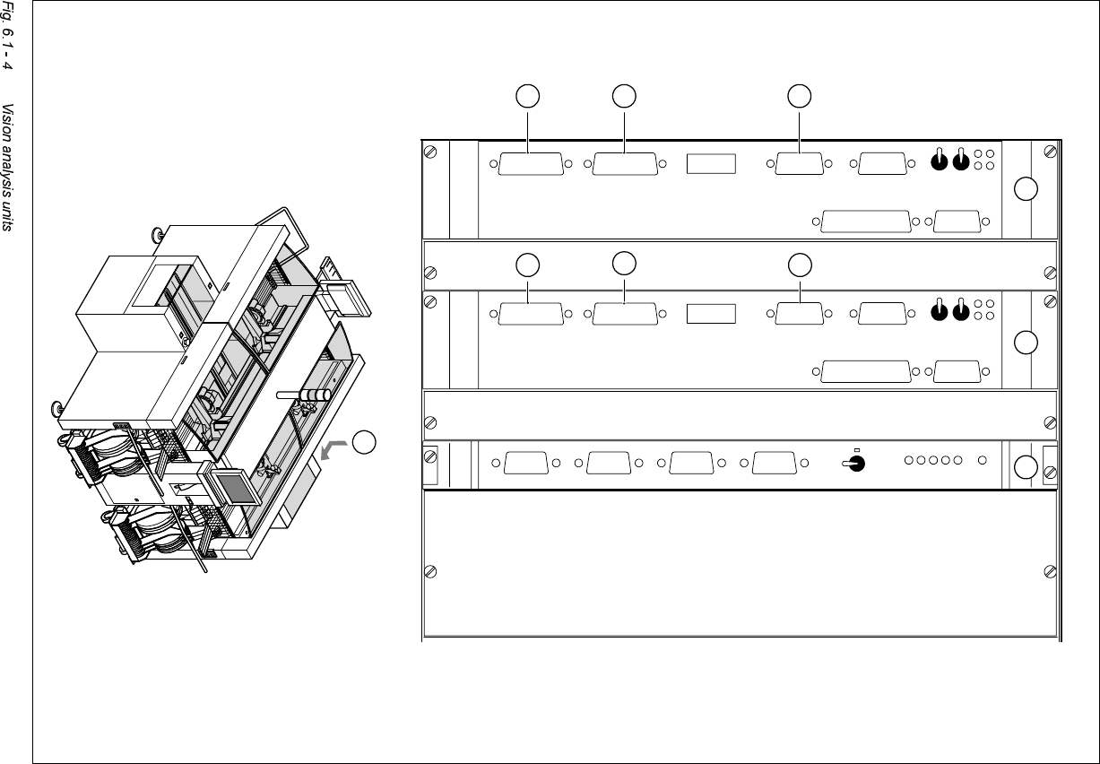
9L VLRQDQDO\VLVXQLWV
The two vision analysis units (see items 1 and 2 in Fig. 6.1 - 4) are plugged into the placement
system’s control unit.
They process and analyze electrical signals from the component and PCB camera systems. Cor-
rection values are calculated from any deviations from setpoint. These values are then used for
recalculating the placement positions and angle of rotation for placement.
The vision analysis units also perform a component identification process. The precise component
pick-up position, which is particularly important for small components, is also determined in the
vision analysis units.
6 Vision functions User Manual HS-50
6.1 The vision systems on the placement system Software-Version 5.01 Edition 01/99
184
4
ICOS 2ICOS 1GEMMC
X4svX3svX2svX1sv
S-COM 1S-COM 2
AUX
VGA
HS3L
X4su
X3su
X6suX7su
X8su
X5suX9su
Abort
Reset
Reset
Abort
X9st X5st X8st
X7st X6st
X3st X4st
HS3L
VGA
AUX
S-COM 2
S-COM 1
Kamera 2/4 Kamera 1/3
Kamera 2/4 Kamera 1/3
1 2 3
9
5
6
10
7
8