00191369-01.pdf - 第326页
7 What schould you do ... User’s Manual S IPLACE HS-50 7.5 When you, as an operator, carry out a walk-through inspec tion Software Version SR.501.xx E dition 01/99 324 Å Check to see if th e addit ional pla stic gui des …
User’s Manual SIPLACE HS-50 7 What schould you do ...
Software Version SR.501.xx Edition 01/99 7.5 When you, as an operator, carry out a walk-through inspection
323
:KHQ\RXDVDQRSHUDWRU FDUU\RXWDZDONWKU RXJ K
LQVSHFWLRQ
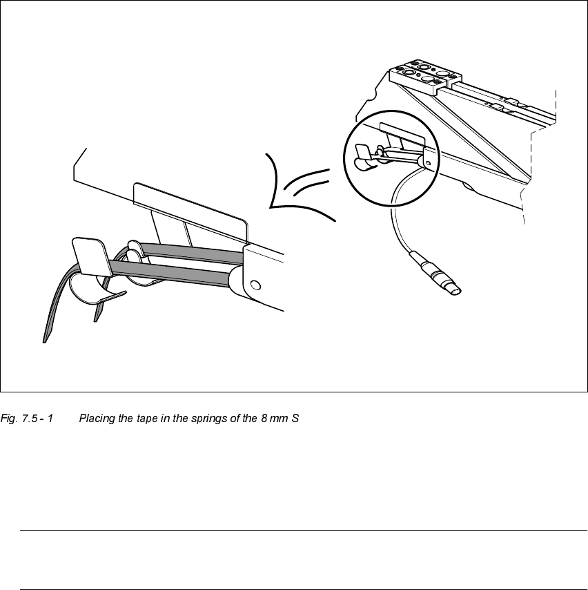
Å Make sure that the tape is correctly placed in the springs of the 8 mm S.
Å Check to ensure that the tape foil removal container for the 8 mm S is full.
If it is full, then pull out the foil and cut it off with scissors.
NOTE
Tearing the foil instead of cutting it can lead problems with the tape removal mechanism.
Å Check to ensure that the withdrawal space on the feeder module is the right size for the com-
ponent.
Å Check to see if tape guides are being used on the feeder modules that are intended for different
tape widths.

7 What schould you do ... User’s Manual SIPLACE HS-50
7.5 When you, as an operator, carry out a walk-through inspection Software Version SR.501.xx Edition 01/99
324
Å Check to see if the additional plastic guides are being used on the feeder modules that are in-
tended for tapes of different widths.
Å Check the position of the stopper on the PCB transport.
Always position the stopper so that it is not placed within any cut-outs or recesses in the PCB.
Å Check the magnetic supports on the lifting table. They must be arranged so that they do not
collide with components on the bottom of the PCBs.
NOTE
Splice the tapes early enough so that the feeder modules do not become empty or you will
experience prolonged down times.
However, do not splice the tapes too early because if you wind the end of the old tape onto
the new reel after splicing, the reel holding the new tape may become overfilled and the tape
will slip off the reel and become tangled up. This will again result in pick-up errors and pro-
longed down times.
Å Place insertable shafts into the tape container when using large tape reels.
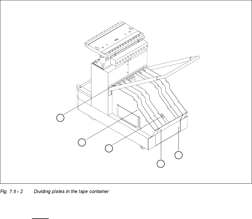
Å Insert the dividing plates as shown in Fig. 7.5 - 2 and remember that the smallest division of the
tape container is a 2x division. This will help avoid placement errors.
User’s Manual SIPLACE HS-50 7 What schould you do ...
Software Version SR.501.xx Edition 01/99 7.5 When you, as an operator, carry out a walk-through inspection
325
.H\WR)LJ
7.5 - 2
(1) Guide rail for the dividing plates
(2) Dividing plate
(3) Supporting rod for the dividing plates
(4) Tape container
(5) Tape waste container
04
6
1
-6
6
1
7
-2
4
3
1
-3
6
2
5
-3
0
4
9
-5
4
5
5
-6
0
4
3
-4
8
+
3
0
V
3
7
-4
2
02
1
-6
7
-1
2
1
3
-1
6
03
01
07 0908
6
7
-7
2
10 11 12
05 06
1
3
5
2
4