00191369-01.pdf - 第189页
User Manual HS-50 6 Vision functions Software-Version 5.01Edition 01/99 6.2 PCB vision system 187 'HVFULS WLRQ R I) XQF WLRQV Before pl acement th e loca tion, s kew an d shear of the boar d is deter mine …
6 Vision functions User Manual HS-50
6.2 PCB vision system Software-Version 5.01 Edition 01/99
186
position of the search field can be programmed as required within the fields of view. The mapping
lens is a special measuring lens which corrects most errors caused by the curvature of the PCB.
The illumination is switched on only while fiducials are being recorded.
The vision analysis unit (MVS) is a single-board system conforming to VME standards. The hard-
ware consists of
– the MVS motherboard with vision processor and interface connections
– and the MVS camera interface for up to four CCD cameras.
096PRWKHUERDUGZLWKYLVLRQSURFHVVRUDQGLQWHUIDFHFRQQHFWLRQV
The two VME bus connections are located on the back of the VME module.
The front panel of the VME module contains connectors for
– the monitor (VGA mode, 15-pin SUBD connector)
– the high-speed interface (HS
3
L), 9-pin SUBD connector
– up to 4 camera inputs (2 x 15-pin SUBD connector)
– two serial interfaces (RS232 for COM1 with a 25-pin SUBD connector and COM2 with a
9-pin SUBD connector)
– trigger and flash signals (10-pin ribbon cable connector)
and status display LEDs for
–the CPU (CFG)
– the vision processor (ACA)
– the camera input (BCA)
– the screen display (DISP)
7HFKQLFDO'DWD
Camera model: SONY XC75
Number of pixels: Camera 768 (H) x 494 (V), Image 640 (H) x 484 (V)
Field of view: 5.7 mm x 5.7 mm
Illumination method: Incident light method (activated during measurement)
Image processing: Correlation principle, gray scale system
Processor cycle time: < 200 msec
Screen: RGB monitor (VGA mode) 640 x 484 pixels in the station computer
Fiducials: Library memory for up to 255 fiducial definitions
User Manual HS-50 6 Vision functions
Software-Version 5.01Edition 01/99 6.2 PCB vision system
187
'HVFULSWLRQ R I) XQFWLRQV
Before placement the location, skew and shear of the board is determined by the PCB vision sys-
tem using the position of the fiducials. Deviations from the setpoint values are then included in the
calculation of the placement positions of the components as corrections.
A board must have at least 2 fiducials if the system is to be able to detect deviations in the board
position and the skew of the board. The presence of 3 fiducials will furnish additional information
concerning compression or stretching of the board or of the board layout.
6HTXHQFHRI)XQFWLRQV
Before a fiducial can be used for board recognition it must first be ’taught’ to the machine. In other
words, the fiducial structure parameters must have been saved in the PCB vision system for that
pattern.
The fiducial structure can be taught using the PCB vision camera mounted on the gantry and the
vision program. The vision analysis unit determines the significant fiducial structure parameters
using digital image processing methods.
Measurement takes place in two stages:
– 2-D pattern search (2-dimensional process) in the coarse grid and provisional determina-
tion of the fiducial coordinates
– 1-D pattern search (1-dimensional process) for a precise determination of the position of
the fiducials.
With the 2-D pattern search process the template window is divided into moxel areas. Moxels
(PRsaic pi[HOs) are pixel fields containing for example 16 x 16, 8 x 8 pixels and so on. The lower
the pixel count the higher the resolution and the lower the search speed.
6 Vision functions User Manual HS-50
6.2 PCB vision system Software-Version 5.01 Edition 01/99
188
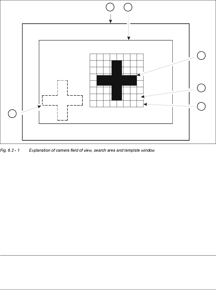
.H\WR)LJ
(1) Camera field of view
(2) Search area
≤
camera field of view (the fiducial is searched for in this area)
(3) Reference fiducial
(4) Moxel = pixel field, eg 16 x 16 pixels
(5) Template window (it contains the reference fiducial)
(6) Fiducial which is to be searched for
The template window is moved over the search area in moxel steps. The gray scale values of each
moxel of the reference fiducial are calculated at this time. This reduced data structure will contain
enough information on the coarse structure and position of the reference fiducial.
NOTE
The search window should be as small as possible in order to keep the speed of searching high.
On the other hand the window should be large enough to allow the fiducial to be identified without
ambiguity.
4
2
5
6
3
1