00191369-01.pdf - 第374页
10 Component handling User M anual HS-50 10.5 Used tape cutter Software-Version 5.01 01/99 Issue 372 )HHGLQJWKHXVHG WD SHWRWKHFXWWHU .H\ WR )LJ (1) Us ed tape guide c hannel (2) Chan nel for re…
User Manual HS-50 10 Component handling
Software-Version 5.0101/99 Issue 10.5 Used tape cutter
371
*HQHUDO
The placement system has a used tape cutter at each of the four component table locations. It is
used to cut off the waste tape. The cut pieces of tape drop into the waste tape container in the
component table.
Å Empty the waste tape container every day.
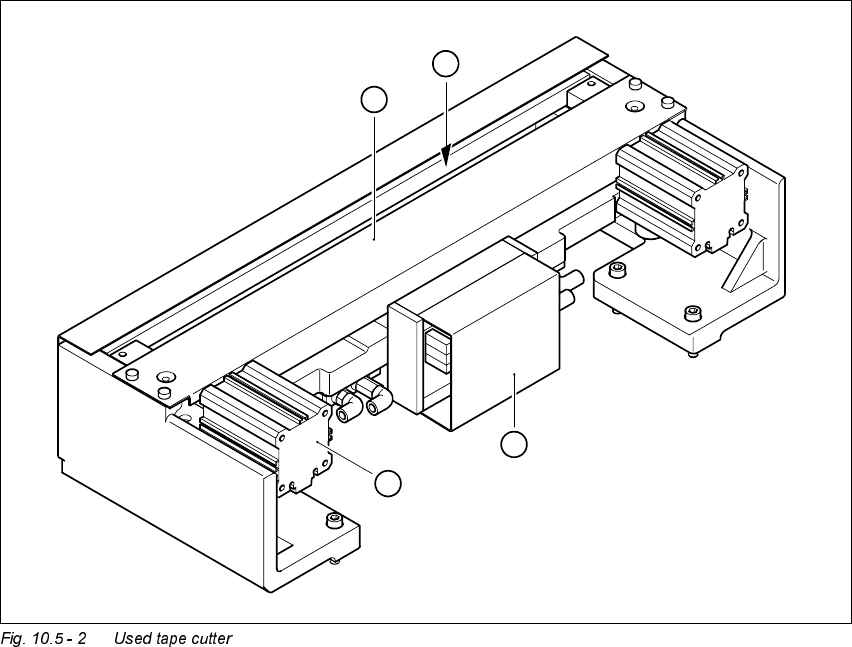
.H\WR)LJ
(1) Pneumatic cutting device
(2) Short-stroke lifting cylinder
(3) Control module
(4) Opening for removal of the used tape
3
2
1
4
10 Component handling User Manual HS-50
10.5 Used tape cutter Software-Version 5.01 01/99 Issue
372
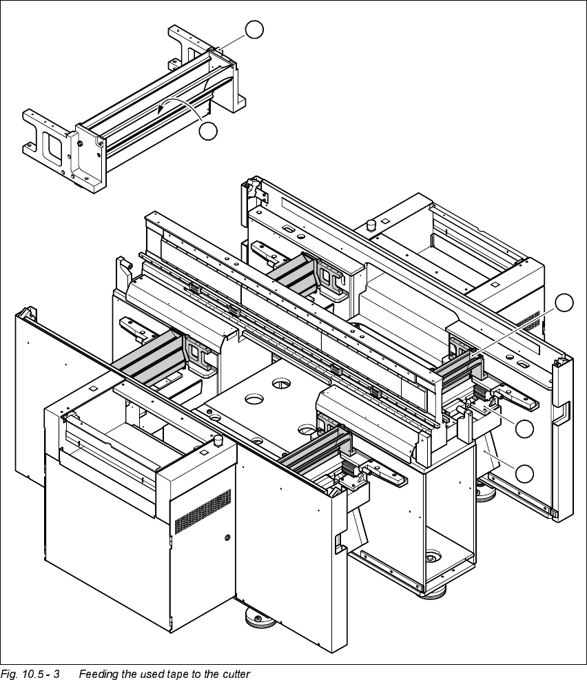
)HHGLQJWKHXVHG WDSHWRWKHFXWWHU
.H\ WR )LJ
(1) Used tape guide channel
(2) Channel for removal of the used tape
(3) Tape cutter
(4) Waste tape chute
1
2
1
3
4
User Manual HS-50 10 Component handling
Software-Version 5.0101/99 Issue 10.5 Used tape cutter
373
The used tape guide channels (see item 1 in Fig. 10.5 - 3) are located upstream of the feeder mod-
ules. They are positioned directly above the used tape cutters (see item 3 in Fig. 10.5 - 3).
The tape is automatically guided through the used tape guide channel into the used tape cutter
below. There, the tape is shredded by the pneumatically-actuated cutting blade. The waste tape
then passes via the waste tape chute (see item 4 in Fig. 10.5 - 3) into the component table’s waste
container.
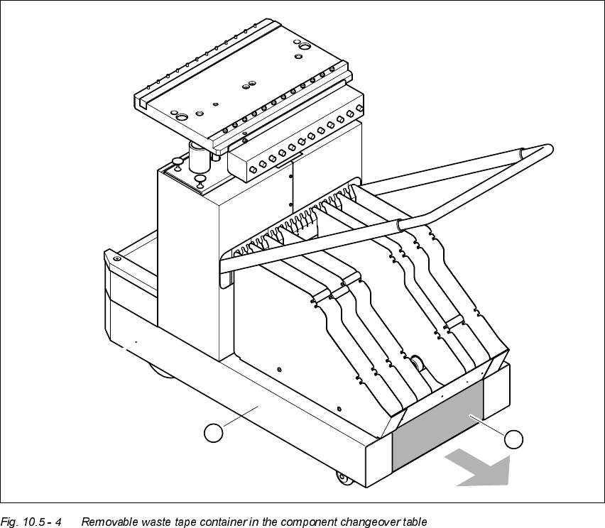
.H\WR )LJ
(1) Component changeover table
(2) Removable waste tape container
2
1