00193922-03.pdf - 第113页
User manual SIPLAC E HF series 3 Technical data Software Vers ion SR.50x.xx 01/2006 US Edition 3. 5 Line concept 113 The SIPLACE S-27 HM i s a high -speed sy stem for pla cing co mponent s from 02 01 to 32 x 32 mm². 3 Th…
3 Technical data User manual SIPLACE HF series
3.5 Line concept Software Version SR.50x.xx 01/2006 US Edition
112
3.5 Line concept
3.5.1 Description
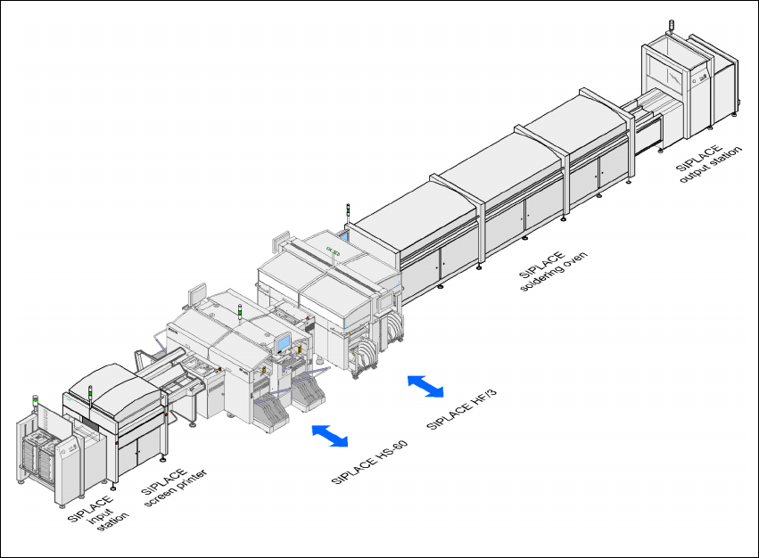
The SIPLACE concept is characterized by its flexibility, modularity, compactness and high power
density. It allows a production line to be individually configured from identical and different mod-
ules. If the production requirements change, the individual placement machines are so compact
that they can be recombined quickly and easily. 3
3
Fig. 3.5 - 1 Sample line concept
3
The SIPLACE family has exactly the right placement machine, whatever the output require-
ments: 3
SIPLACE HF and HF/3 placement machines can be used to place IC, flip-chip, bare die and
exotic components (OSC). They cover the spectrum of components from 0201 to 85 x 85 / 125
x 10 mm² with a high placement rate. 3
The SIPLACE HS-60 is a super high-speed placement machine for processing components
ranging from 0201 through to 18.7 x 18.7 mm². 3
User manual SIPLACE HF series 3 Technical data
Software Version SR.50x.xx 01/2006 US Edition 3.5 Line concept
113
The SIPLACE S-27 HM is a high-speed system for placing components from 0201 to 32 x
32 mm². 3
The SIPLACE F5 HM high-speed system places large ICs, flip-chips, bare dies and exotic com-
ponents (OSC). The component sizes range from 0201 to 55 x 55 mm² 3
3.5.2 SIPLACE set-up optimization
The SIPLACE set-up optimization increases the productivity of your line since it minimizes place-
ment times and non-productive times for your placement machines. The set-up software calcu-
lates individual set-ups for individual products, individual set-ups for different products and family
set-ups for different products. The program data can be exchanged between the individual lines
- even for different machine configurations. 3
3 Technical data User manual SIPLACE HF series
3.6 Overview of the modules Software Version SR.50x.xx 01/2006 US Edition
114
3.6 Overview of the modules
3
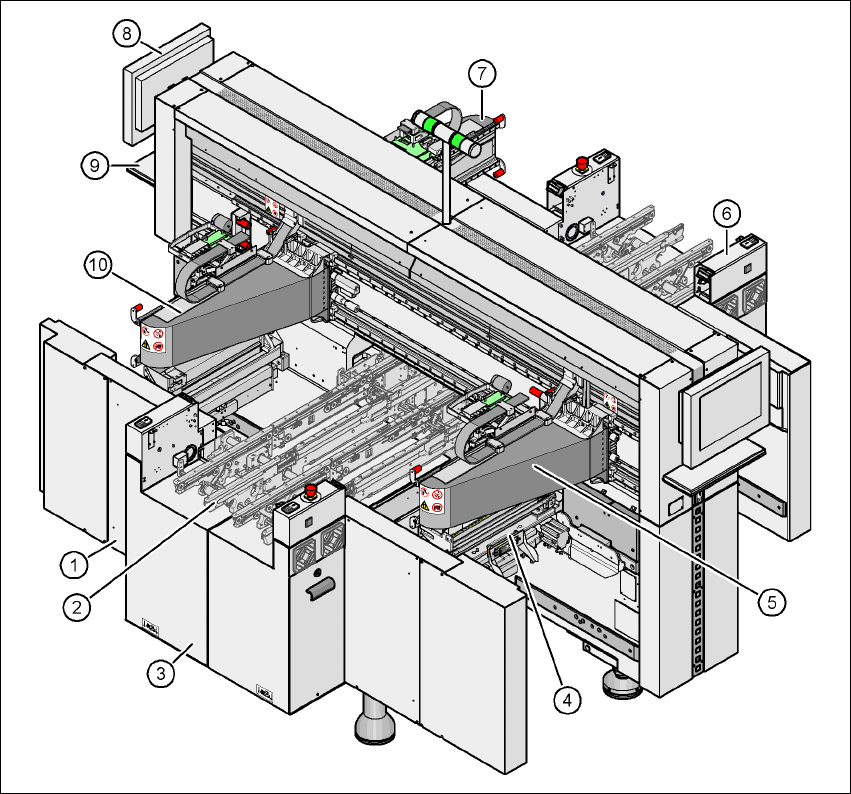
Fig. 3.6 - 1 HF/3 machine - protective covers and cover
(1) Machine frame
(2) PCB conveyor (flexible dual conveyor)
(3) Extension kit on the PCB input side
(4) Component trolley docking unit, tape cutter, used tape channel (4x)
(5) Gantry 1 with placement head (HF and HF/3)
(6) Extension kit on the PCB output side
(7) Gantry 3 with placement head (HF and HF/3)
(8) Monitor (2x)
(9) Keyboard (2x)
(10) Gantry 4 with placement head (HF/3)