00193922-03.pdf - 第233页
User manual SIPLAC E HF series 5 T asks on the m achine Software Vers ion SR.50x.xx 01/2006 US Edition 5.4 Setting up the feeder m odules 233 5.4 Settin g up the feed er modules 5 Fig. 5.4 - 1 Com ponent feeder t able wi…
5 Tasks on the machine User manual SIPLACE HF series
5.3 Carrying out a walk-through inspection Software Version SR.50x.xx 01/2006 US Edition
232
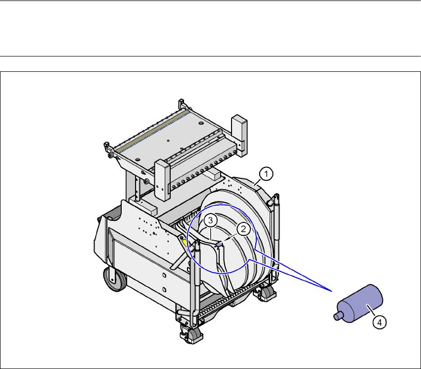
5.3.5 Using spindles for large tape reels
Æ Insert spindles into the separating plates when using large tape reels.
PLEASE NOTE
We recommend that you use spindles if the tape reel diameter exceeds 15" (381 mm)". This will
ensure that the feeder modules operate reliably.
5
Fig. 5.3 - 3 Inserting spindles for large reels
5
(1) Component trolley
(2) Position of the spindles
(3) Separating plate
(4) Spindle (enlarged)
User manual SIPLACE HF series 5 Tasks on the machine
Software Version SR.50x.xx 01/2006 US Edition 5.4 Setting up the feeder modules
233
5.4 Setting up the feeder modules
5
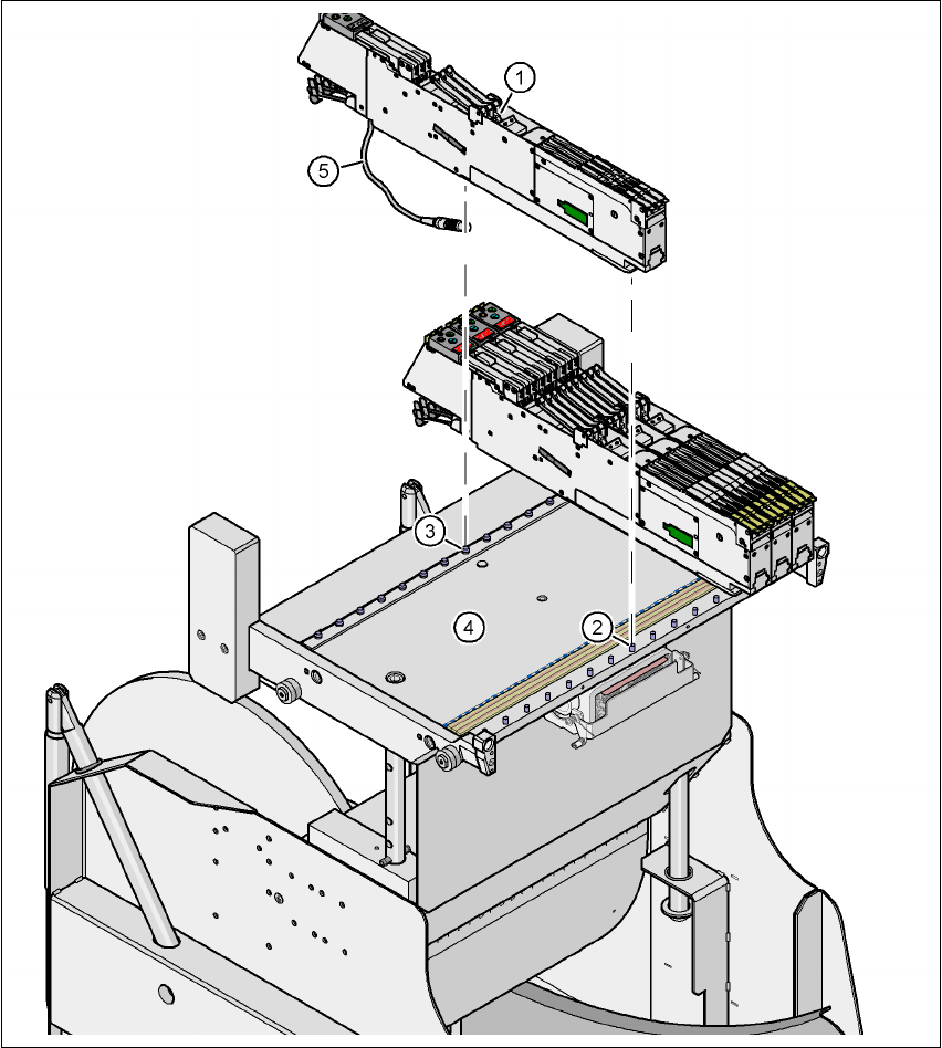
Fig. 5.4 - 1 Component feeder table with 15 locations for S feeder modules
(1) S feeder module
(2) Centering pin
(3) Centering ball
(4) Component feeder table
(5) Connecting cable for the S feeder module
5 Tasks on the machine User manual SIPLACE HF series
5.4 Setting up the feeder modules Software Version SR.50x.xx 01/2006 US Edition
234
5.4.1 Preparing the component feeder table and S feeder modules for set-up
Æ Clean the contact surface for the feeder module.
Æ Clean the contact surface on the component feeder table.
Æ Remove loose components from the component feeder table with a brush or use a vacuum
cleaner with appropriate nozzle.
CAUTION 5
Avoid removing components from the component table with your fingers. You may hurt your-
self with tiny splinters of metal.
5.4.2 Inserting the S feeder modules
Æ First place the front of the feeder module (item 1 in Fig. 5.4 - 1), i.e. the side with the slotted
foot, onto the component feeder table (item 4 in Fig. 5.4 - 1
) so that the centering pin (item 2)
on the component feeder table slides into the slot in the feeder module foot.
Æ Then lower the back of the feeder module until the centering ball (item 3 in Fig. 5.4 - 1) dis-
appears into the hole in the feeder module.
Æ Make sure that the feeder modules are placed correctly on the component feeder table to suit
their width (see Fig. 5.4 - 2
).
Æ Check that the feeder module is firmly seated on the component feeder table.
Æ Connect the feeder module plug (item 5 in Fig. 5.4 - 1) to the socket beneath the location.
PLEASE NOTE 5
When you connect the feeder module, make sure that you use the right socket for the location
since the feeder module receives the control pulse via this socket. The feeder module may
not work correctly if it is not connected to the right socket. The user manual for the feeder
modules used will contain detailed information on the assignment of plugs to sockets.