00193922-03.pdf - 第84页
2 Operational safety User manual SIPLACE HF series 2.9 Energy state of the machine af ter switching off at t he main power switch Software Vers ion SR.50x.xx 01/2006 US E dition 84 The foll owing table s pecifies th e vo…
User manual SIPLACE HF series 2 Operational safety
Software Version SR.50x.xx 01/2006 US Edition 2.9 Energy state of the machine after switching off at the main power switch
83
2
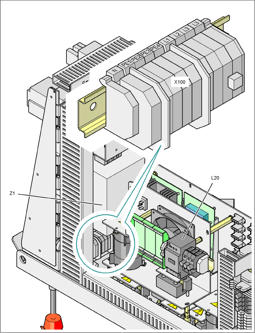
Fig. 2.9 - 5 Power supply unit, back view
2
X100 Cable connection terminal for the power supply cable
L20 Discharge reactor with fuses F21, F22 and F23
Z1 Line filter
2 Operational safety User manual SIPLACE HF series
2.9 Energy state of the machine after switching off at the main power switch Software Version SR.50x.xx 01/2006 US Edition
84
The following table specifies the voltages of modules when the automatic placement system is
switched off at the main switch, but still connected to the mains supply.
2
Module Voltage
Terminal panel X100
Line filter Z1
Terminals L1, L2, L3
3 x 208 VAC
3 x 230 VAC
3 x 380 VAC
3 x 400 VAC
3 x 415 VAC
Service socket X102
120 VAC
130 VAC
220 VAC
230 VAC
240 VAC
F1 automatic circuit breaker
120 VAC
130 VAC
220 VAC
230 VAC
240 VAC
Main switch Q1
Terminals L1, L2, L3
3 x 208 VAC
3 x 230 VAC
3 x 380 VAC
3 x 400 VAC
3 x 415 VAC
Main switch Q1
Terminals T1, T2, T3
0 VAC
Power supply unit (see item 5 in Fig. 2.7 - 2
)
Test socket X11
GND X12
Test socket X13_1
Test socket X13_4
GND X13_7
< 10 VDC
< 10 VDC
< 10 VDC
Computer unit (see Fig. 2.9 - 3
)
Test socket + 12 VDC
Test socket - 12 VDC
Test socket + 15 VDC
Test socket -15 VDC
Test socket + 5 VDC
Test socket + 52 VDC
Test socket + 3.3 VDC
GND
0 VDC
0 VDC
0 VDC
0 VDC
0 VDC
0 VDC
0 VDC

User manual SIPLACE HF series 2 Operational safety
Software Version SR.50x.xx 01/2006 US Edition 2.10 Lock out and tag out procedure
85
2.9.2 Placement system switched off at the main power switch and
disconnected ...
The automatic placement system is unpowered, apart from slight residual voltages in the power
supply unit.
2.9.3 Compressed air conditions in the machine after switching off at the main
power switch
When the system is switched off at the main power switch (item 1 in Fig. 2.9 - 1) or if the power
supply fails, the electrically-controlled main valve Y1 of the compressed air unit closes (item 1 in
Fig. 2.8 - 1
). The pressure will drop to 0 MPa (0 bar) within 5 seconds.
2.10 Lock out and tag out procedure
2.10.1 Purpose and scope
Before performing any preventive maintenance work or service work, a procedure of locking and
tagging must be followed. The procedure, when followed correctly eliminates the possibility of an
employee being injured.
PLEASE NOTE
These procedures represent the minimum lock/tag out requirements. Any additional safeguards
needed to complete work safely can be specified by facilities supervision, the safety officer, the
safety committee and the health department. 2
2.10.2 Description
Whenever it becomes necessary to isolate, control and release energy, the following procedure is
to be followed
Æ Notify affected employees.
Æ Shut down the equipment. Carry out all normal stopping procedures:
– Press the Stop button.
– Shut down the station computer.
– Switch the placement machine off at the main power switch.