00193922-03.pdf - 第205页
User manual SIPLAC E HF series 4 Setting up and commissioning Software Vers ion SR.50x.xx 01/2006 US Edition 4.4 Setting up the placement machine 205 4.4.10.5 Fitting the gr ounding cable for t he doors Æ F ix the tw o g…

4 Setting up and commissioning User manual SIPLACE HF series
4.4 Setting up the placement machine Software Version SR.50x.xx 01/2006 US Edition
204
Æ Introduce the mandrel (item 5 in Fig. 4.4 - 16) of the conveyor cover into the hole (item 6 in
Fig. 4.4 - 16
) in the second half of the extension kit.
Æ Position the second half of the extension kit so that the assembly bracket lies on the assembly
bar (item 7 in Fig. 4.4 - 15
).
Æ Fix the second half of the machine using 2 fillister head screws M6x16 and washers (item 3
in Fig. 4.4 - 15
).
4.4.10.3 Fixing the hexagonal shaft guide
Æ On the single conveyor, fix
one
guide for the hexagonal shaft (item 8 in Fig. 4.4 - 14) to the
extension kit using two fillister head screws M6x16 and washers.
Æ On the double conveyor, fix two guides for the hexagonal shaft (item 8 in Fig. 4.4 - 14) to the
extension kit using two fillister head screws M6x16 and washers.
4.4.10.4 Connecting the power cables - Extension kit on the PCB input side
4
4
Left-hand side of the extension kit
(viewed in the direction of travel)
Connector/cable To connector/cable
Start/Stop button
Switch, PCB conveyor cover
X61/03020410 X61/03002537
Protective cover switch, location 4 X54/03020409 X54/03002540
Button for the component trolley docking unit,
location 4
X242/03021056 X242/03021054
Right-hand side of the extension kit
(viewed in the direction of travel)
Connector/cable To connector/cable
Emergency stop button
Start/Stop button
X64/03020687 X64/03002538
Protective cover switch, location 1 X51/03020409 X51/03002539
Button for the component trolley docking unit,
location 1
X212/03021056 X212/03021051
User manual SIPLACE HF series 4 Setting up and commissioning
Software Version SR.50x.xx 01/2006 US Edition 4.4 Setting up the placement machine
205
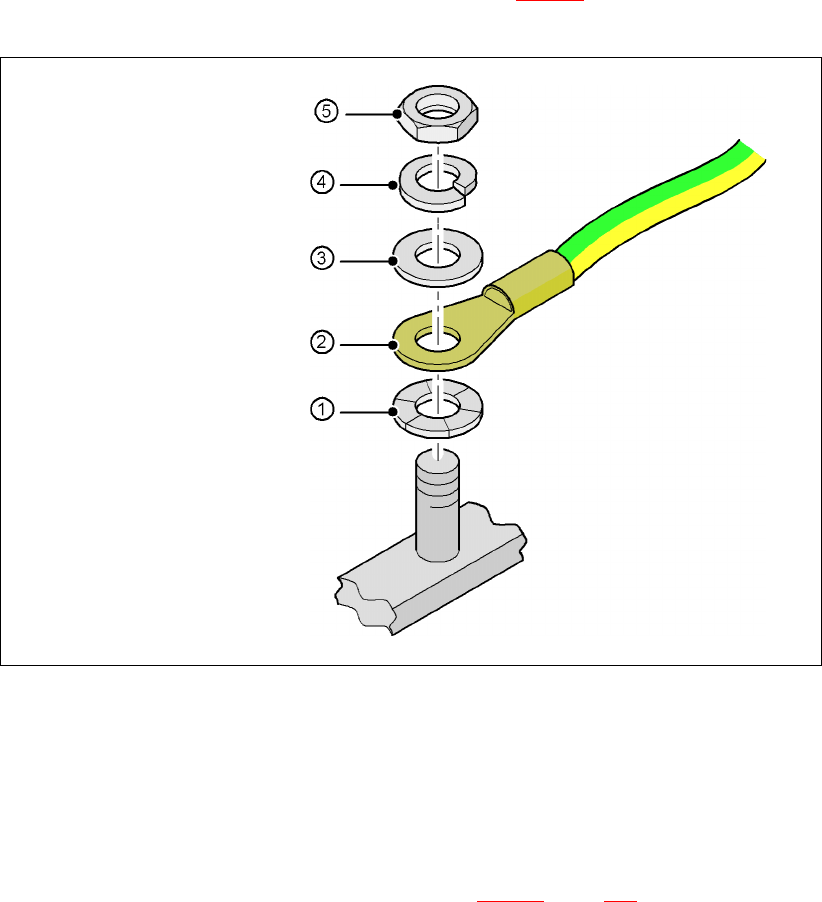
4.4.10.5 Fitting the grounding cable for the doors
Æ Fix the two grounding cables for the doors (item 4 in Fig. 4.4 - 15) to the machine frame as
follows:
4
Fig. 4.4 - 17 Fitting the grounding cable
4
4
4
4
4
4.4.10.6 Checking and setting the protective cover switch
Æ Check that the protective cover switch (item 7 in Fig. 4.4 - 16, page 203) is working correctly.
Æ Adjust the protective cover switch if necessary (see Service Manual).
4
Hex nut M5
Spring washer M5, DIN 7980
Washer M5, DIN 125
Cable lug, annular
Contact washer
4 Setting up and commissioning User manual SIPLACE HF series
4.4 Setting up the placement machine Software Version SR.50x.xx 01/2006 US Edition
206
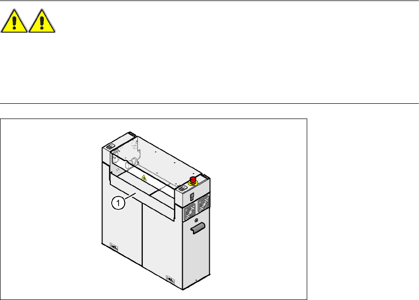
4.4.10.7 Installing the "bottom" hand guard
The machines from the HF series are supplied with just
one
"bottom" hand guard. If the machines
are installed within a line, then no hand guard is required between immediately adjacent output
and input conveyors.
WARNING
Always fit the "bottom" hand guard (item no. 03003432-01) on the input side of the
first
place-
ment machine and on the output side of the
last
placement machine of a line using 4 hexagon
socket head screws M4x12. This will prevent your personnel reaching into the machine without
authorization.
4
Fig. 4.4 - 18 Fitting the "bottom" hand guard on the PCB input side
(1) "Bottom" hand guard, item no. 03003432-01