00193922-03.pdf - 第148页
3 Technical data User manual SIPLACE HF series 3.11 Vision modules S oftware Version SR .50x.xx 01/2006 US Edition 148 3.1 1.3 Component vision camera for the T winHead 3.1 1.3.1 Structu re of the component vision camera…
User manual SIPLACE HF series 3 Technical data
Software Version SR.50x.xx 01/2006 US Edition 3.11 Vision modules
147
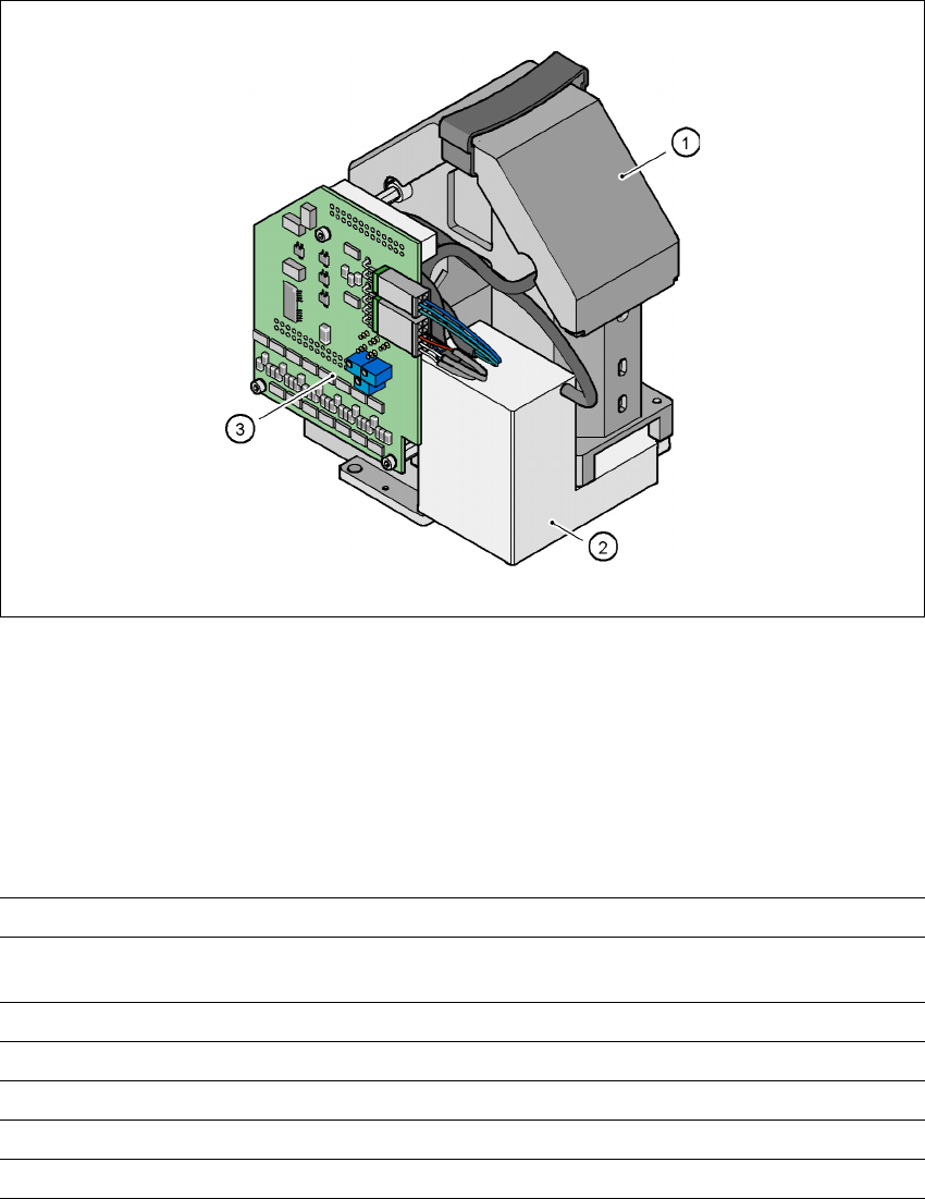
3.11.2 Component vision camera (39 x 39) on the 6-segment Collect&Place head
3.11.2.1 Structure
3
Fig. 3.11 - 3 Component vision camera (39 x 39) on the 6-segment Collect&Place head
3
(1) Component camera lens and illumination
(2) Camera amplifier
(3) Illumination control
3.11.2.2 Technical data
3
Component dimensions 1.6 x 0.8 mm² to 32 x 32 mm²
Range of components 0603 to 32x32mm²
PLCC, SO, QFP, TSDP, SOT, MELF, CHIP, IC BGA
Min. lead pitch 0.5 mm
Min. bump pitch 0.56 mm
Min. ball/bump pitch 0.32 mm
Field of vision 39 x 39 mm²
Method of illumination Front lighting (three levels, programmable as required)
3 Technical data User manual SIPLACE HF series
3.11 Vision modules Software Version SR.50x.xx 01/2006 US Edition
148
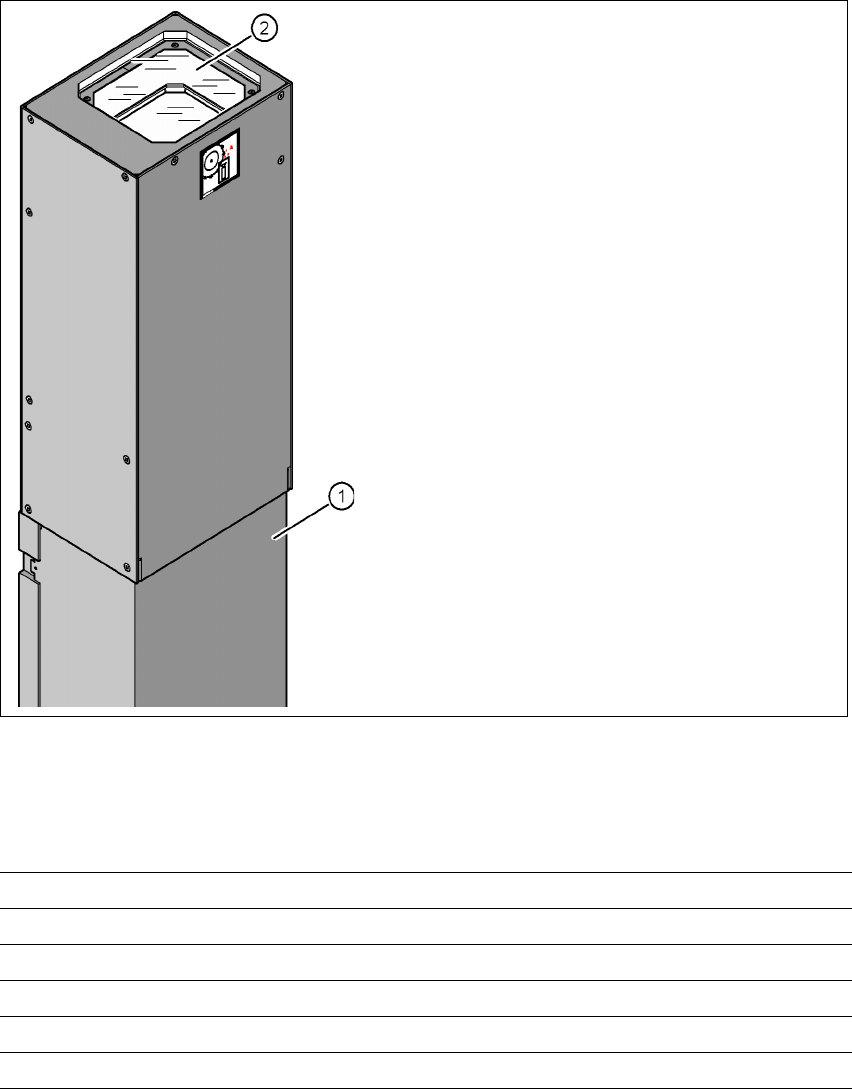
3.11.3 Component vision camera for the TwinHead
3.11.3.1 Structure of the component vision camera (stationary, P&P (type 22) 50 x 40)
3
Fig. 3.11 - 4 Structure of the component vision camera (stationary, P&P (type 22) 50 x 40)
3.11.3.2 Technical data
3
(1) Camera housing with integral camera and
camera amplifier
(2) Glass plate - over the illumination and lens
levels
Component dimensions Up to 50 x 40 mm² for a single component measurement
Range of components 0603, MELF, SO, PLCC, QFP, electrolytic capacitors, BGA
Min. lead pitch 0.4 mm
Min. ball/bump diameter 0.32 mm
Field of vision 60 x 45 mm²
Method of illumination Front-lighting (6 levels, programable as required)
User manual SIPLACE HF series 3 Technical data
Software Version SR.50x.xx 01/2006 US Edition 3.11 Vision modules
149
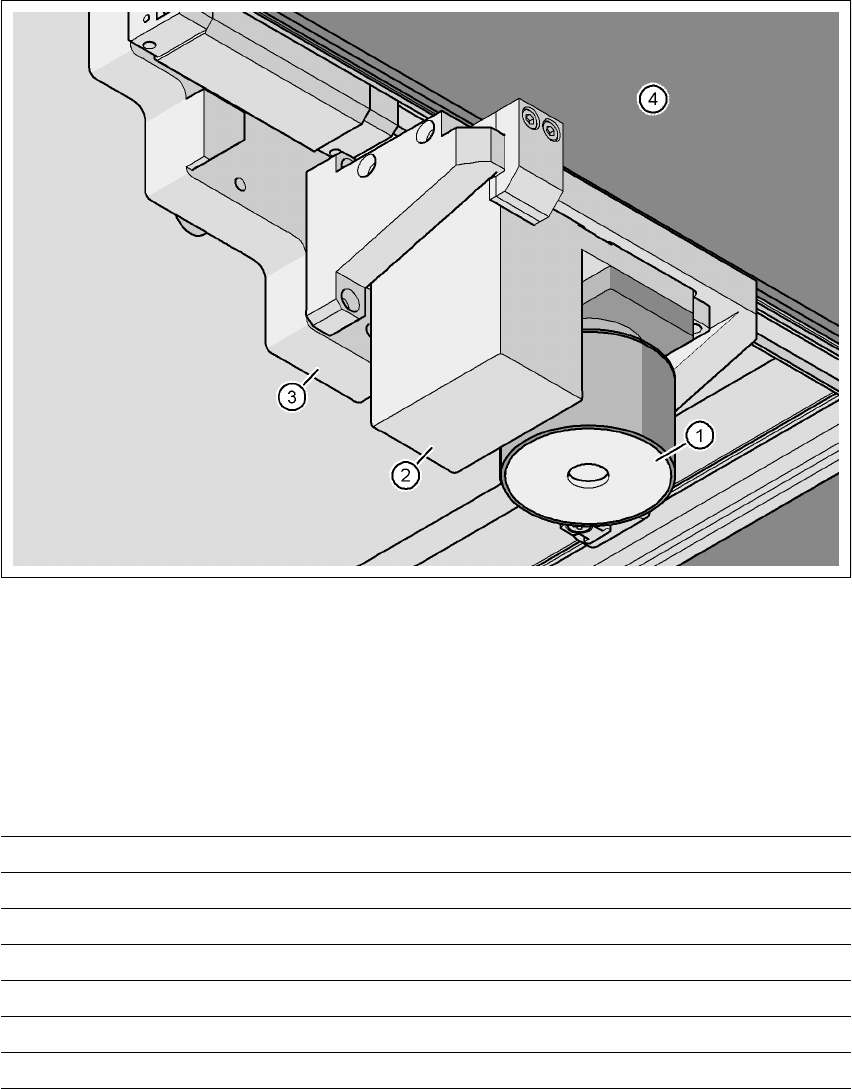
3.11.4 PCB vision camera, standard (type 5)
3.11.4.1 Position
3
Fig. 3.11 - 5 PCB vision camera, standard (type 5) on the gantry - view from below
(1) PCB camera lens and illumination
(2) Camera amplifier
(3) Head mount
(4) Gantry
3.11.4.2 Technical data
PCB fiducials Up to 3 (subpanels and multiple panels)
Local fiducials Up to 2 per PCB (may be of different types)
Library size Up to 255 fiducial types - system fiducials ≥ 249
Image processing Geometric alignment
Method of illumination Front-lighting
Detection time per fiducial/bad fiducial 0.4 s
Field of vision 5.7 x 5.7 mm²