00193922-03.pdf - 第229页
User manual SIPLAC E HF series 5 T asks on the m achine Software Vers ion SR.50x.xx 01/2006 US Edition 5.3 Carrying out a walk -through inspection 229 5.3 Car rying out a walk-thr ough inspection 5.3.1 Checking the S fee…

5 Tasks on the machine User manual SIPLACE HF series
5.2 Changing shift Software Version SR.50x.xx 01/2006 US Edition
228
5.2 Changing shift
Æ Splice the tapes early. The feeder modules do not have to be refilled as soon as the new shift
starts. This avoids extended down times.
Æ At the shift change, pass important information on to the next operator. This includes, for in-
stance, changes to the placement program. Also read through the list of the descriptions of
the steps to take in section 5.5
.
Æ Carry out a set-up check.
Make sure that the feeder modules are equipped with the correct components and that they
are at the correct locations in the component trolley.
PLEASE NOTE
Hand over the line in the same state that you would want to find it in when starting your shift.
This means that: 5
– The rejection containers are empty.
– The waste containers are empty.
– The feeder areas have been cleaned with a vacuum cleaner.
User manual SIPLACE HF series 5 Tasks on the machine
Software Version SR.50x.xx 01/2006 US Edition 5.3 Carrying out a walk-through inspection
229
5.3 Carrying out a walk-through inspection
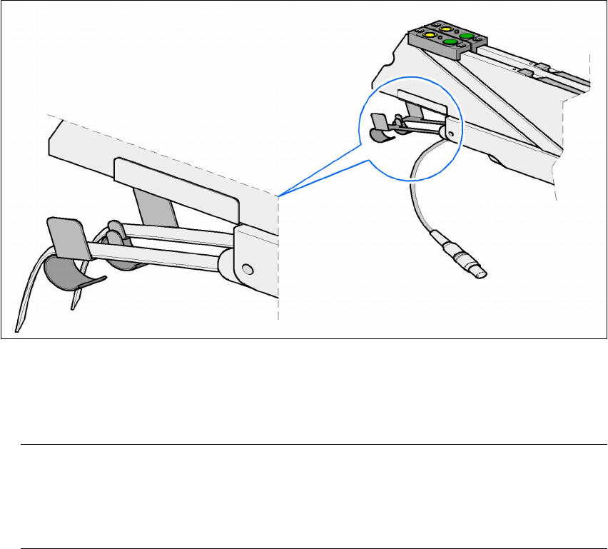
5.3.1 Checking the S feeder modules
Æ Make sure that the tape is correctly placed in the springs of the S feeder module.
5
Fig. 5.3 - 1 Placing the tape in the springs of the S feeder module
Æ Check to see whether the tape foil removal container for the S feeder module is full.
If it is full, then pull out the foil and cut it off with scissors.
PLEASE NOTE
Tearing the foil instead of cutting it can lead to problems with the tape removal mechanism.
For this reason the 3 x 8 mm feeder modules are fitted with an integral cutter. This is in the
tape foil removal container at the end of the feeder module under the flaps. 5
Æ Check to ensure that the pick-up window on the feeder module is the right size for the com-
ponent.
Æ Check to see whether tape guides are inserted on combination feeder modules (24 mm /
32 mm).
Æ Check to see whether the additional plastic guide is inserted on combination feeder modules.

5 Tasks on the machine User manual SIPLACE HF series
5.3 Carrying out a walk-through inspection Software Version SR.50x.xx 01/2006 US Edition
230
5.3.2 Splicing the tape in good time
PLEASE NOTE:
Splice the tapes early enough so that the feeder modules do not run out of components. Oth-
erwise you will experience prolonged down times.
However, do not splice the tapes too early because if you wind the end of the old tape onto
the new reel after splicing, the reel holding the new tape may become overfilled and the tape
will slip off the reel and become tangled up. This will again result in pick-up errors and pro-
longed down times. 5
5.3.3 Checking the PCB supports
Æ
Check the position of the magnetic PCB supports on the lifting table:
– Make sure that the PCB supports do not collide with components on the underside of the
PCBs.
– In addition, make sure that the PCB supports do not collide with the PCB conveyor pan-
els.
5.3.4 Inserting separating plates in the tape container
Æ The separating plate has different edges and can be inserted into the tape container in two
ways. If spindles are used, the recesses for the spindles in the separating plate point upwards
(see item 6 in Fig. 5.3 - 2
). If you do not use spindles, the rounded edge of the separating plate
points up (see item 5 in Fig. 5.3 - 2
).
Æ Insert the separating plates as shown in Fig. 5.3 - 2 and remember that the smallest division
of the tape container is a 2x division. This will help avoid placement errors.
Æ Check that the separating plates engage in the same positions on the three guide rails. Oth-
erwise the separating plate will be offset or bent.