00193922-03.pdf - 第322页
7 Station extensions User manual SIPLA CE HF series 7.4 Component barc ode scanner Software Version SR.50x.xx 01/2006 US Edition 322 three digits spe cify the trac k number . The re are al so return ba rcodes at both end…
User manual SIPLACE HF series 7 Station extensions
Software Version SR.50x.xx 01/2006 US Edition 7.4 Component barcode scanner
321
7.4 Component barcode scanner
7.4.1 General
Item no. 00119683-xx
With the placement system, a barcode scanner can be used to check that the track allocation is
correct and to read component data from component reels. A barcode scanner can be installed
on both of the operator panels on the placement system. A retrofit kit contains two component bar-
code scanners.
7
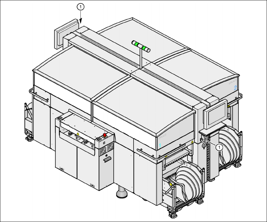
Fig. 7.4 - 1 Component barcode scanner
(1) Barcode scanner
Track allocation 7
Four-digit barcode strips are attached to the lateral safety screens for the purposes of track allo-
cation. The first digit is used to identify the component table (1, 2, 3, or 4), while the remaining

7 Station extensions User manual SIPLACE HF series
7.4 Component barcode scanner Software Version SR.50x.xx 01/2006 US Edition
322
three digits specify the track number. There are also return barcodes at both ends of the barcode
strip. The barcode strips are numbered consecutively in intervals of two (1, 3, 5, 7...) and each
represents 2 tracks (barcode 1 = track 1 and 2).
Components 7
Data can be read from the component reels to compare the stock of components against the quan-
tity specified in the set-up file (refill check), for example.
An audible signal is given when each dataset has been read successfully.
PLEASE NOTE 7
The component barcode scanner option must be configured on the SIPLACE Pro computer.
Barcodes that start with the number 1, 2, 3, or 4 and are 4 digits long are interpreted as track bar-
codes. All other barcodes that do not start with number 1, 2, 3, or 4 are regarded as component
barcodes.
7.4.2 Technical data
7
Component barcode scanner
Max. resolution 0.13 mm
Scanning speed 36 scans/sec.
Laser class Laser class 1
Degree of protection IP 64
Dimensions 225 x 69 x 67 mm³
Weight 380 g
Cable length 2 m
Influence of ambient light Immune to the direct incidence of normal light and the
indirect incidence of sunlight
Operating temperature - 10°C to + 40°C
Atmospheric humidity Max. 90% (non-condensing)
Compatible barcode types Code 39 (normal / FULL ASCII)
EAN/UPC (family with/without ADD ON
CODABAR
INTERLEAVED 2/5
NORMAL 2/5 (5 bars)
(others available upon request)
User manual SIPLACE HF series 7 Station extensions
Software Version SR.50x.xx 01/2006 US Edition 7.5 PCB barcode scanner
323
7.5 PCB barcode scanner
7.5.1 Overview
Item no. 00119682-xx 1D PCB barcode scanner
Item no. 00119679-xx 2D PCB barcode scanner
Item no. 00119684-xx PCB barcode scanner assembly kit
The PCB barcode scanner is used to automatically record and decode barcodes on PCBs. The
PCB barcode scanner sends the read data via its serial interface to the transport controller and
then for further processing to the machine controller via the CAN bus.
7
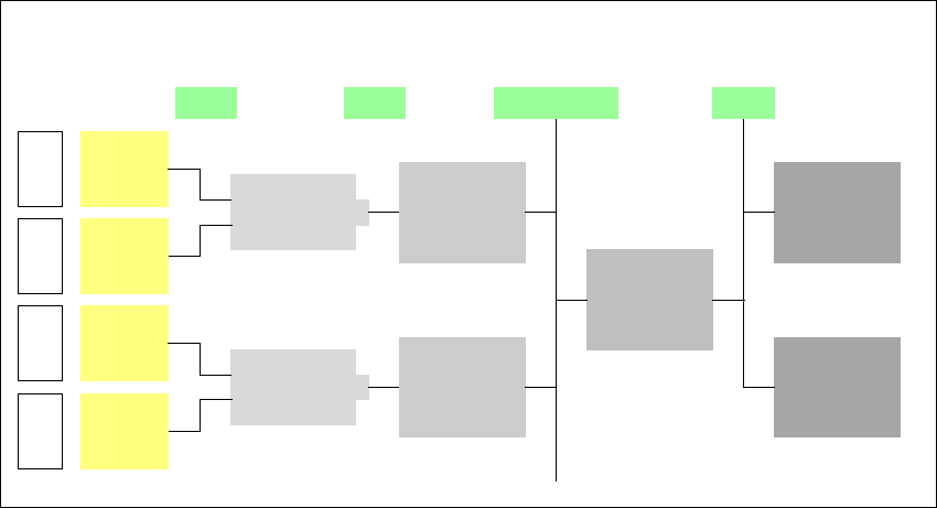
Fig. 7.5 - 1 PCB barcode block diagram
The PCB barcode scanners are installed on the input side of the placement machine on the PCB
conveyor. Up to four devices can be retrofitted to each machine. The barcode scanners are fitted
so that the barcode labels on the topside and underside of the PCBs can be scanned on both
tracks of the dual conveyor.
There are two variants of the barcode scanner:
– 1D barcode scanner
This barcode scanner processes barcodes. 7
– 2D barcode scanner
This barcode scanner processes matrix code. Matrix code is primarily used when there
is not enough space for barcode labels. The 2D barcode scanner also reads conven-
tional barcodes. 7
Device number
1
Barcode
scanner
topside
Distribution
board
Transport
controller,
right
Barcode
scanner
underside
2
3
Barcode
scanner
topside
Distribution
board
Transport
controller,
left
Barcode
scanner
underside
4
Machine
controller
Station
computer
SIPLACE Pro
computer
LANCAN busV-24V-24