00193922-03.pdf - 第314页
7 Station extensions User manual SIPLA CE HF series 7.1 Nozzle changer Software Version SR.50x.xx 01/2006 US E dition 314 7.1.3.4 Ass embly The nozz le chan ger is fixed to the c omponent tr olley docking unit. 7 Fig. 7.…
User manual SIPLACE HF series 7 Station extensions
Software Version SR.50x.xx 01/2006 US Edition 7.1 Nozzle changer
313
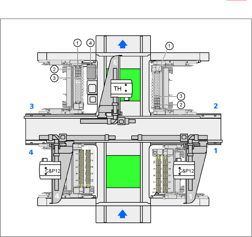
7.1.3.3 Position of the nozzle changers for the TwinHead on the HF/3 machine
A nozzle changer for the TwinHead may be installed at locations 2 and 3 (item 1 in Fig. 7.1 - 19).
This gives a total capacity of 2 nozzle changers and a total of 48 nozzle holders.
7
Fig. 7.1 - 19 Position of the nozzle changers for the TwinHead on the HF/3 machine
(1) Nozzle changer
(2) Standard magazine
(3) Magazine for special nozzles or grippers
(4) Component reject bin
7 Station extensions User manual SIPLACE HF series
7.1 Nozzle changer Software Version SR.50x.xx 01/2006 US Edition
314
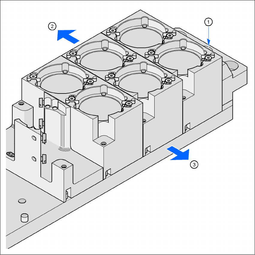
7.1.3.4 Assembly
The nozzle changer is fixed to the component trolley docking unit.
7
Fig. 7.1 - 20 Assembly position
(1) Marking hole
(2) Operator side
(3) Arrow pointing toward the PCB conveyor
7
Æ Align the nozzle changer so that the marking hole (item 1) is on the left, as viewed by the op-
erator.
User manual SIPLACE HF series 7 Station extensions
Software Version SR.50x.xx 01/2006 US Edition 7.1 Nozzle changer
315
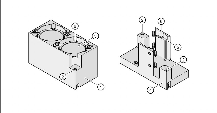
7.1.3.5 Description of the functions
The magazine for standard nozzles has 1 positioning fiducial for position detection, while the mag-
azine for special nozzles/grippers has two. The nozzles are fixed by balls in the holder. They are
then either clamped or released for removal, depending on the direction of rotation of the DP axis.
7
Fig. 7.1 - 21 Magazine for standard and special nozzles
(1) Standard magazine
(2) Positioning fiducial
(3) Nozzle garage
(4) Magazine for special nozzles and grippers
(5) Nozzle garage
(6) Balls for fixing the nozzles