00193922-03.pdf - 第319页
User manual SIPLAC E HF series 7 Station extensions Software Version SR.50x.xx 01/2006 US Edition 7.3 Component camera for the TwinHead, FC camera 319 7.3.1.2 Position of the component vision cameras for the T w inHead o…
7 Station extensions User manual SIPLACE HF series
7.3 Component camera for the TwinHead, FC camera Software Version SR.50x.xx 01/2006 US Edition
318
7.3 Component camera for the TwinHead, FC camera
7.3.1 Structure of the component camera stationary P&P, type 20, 8 x 8 (FC camera)
Item no. 00119618-xx
7
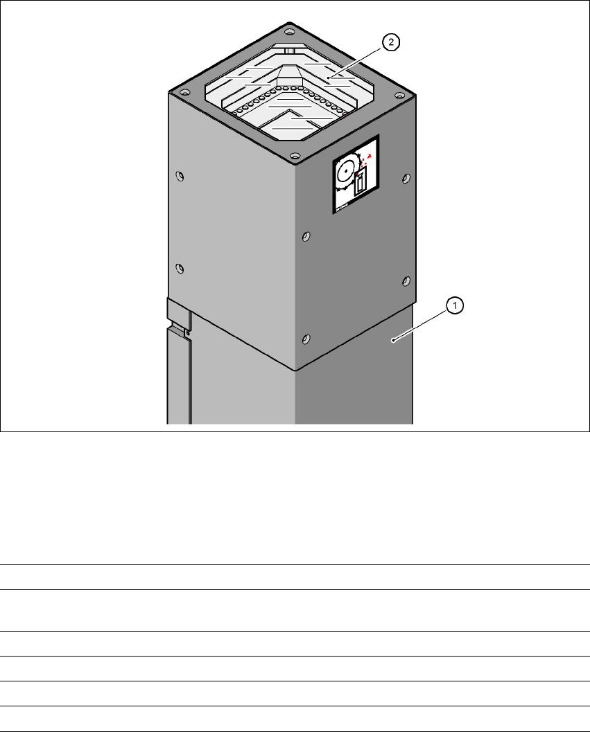
Fig. 7.3 - 1 CO camera stationary P&P, type 20, 8 x 8 (FC camera)
(1) Camera housing with integral camera and camera amplifier
(2) Glass plate - over the illumination and lens levels
7.3.1.1 Technical data
7
Component dimensions 0.6 x 0.3 mm² up to 8 x 8 mm² for single component measurement
Range of components 0201 to SO, PLCC, QFP, sockets, plugs, BGA, special compo-
nents, bare dies, flip-chips, shields
Min. lead pitch 0.25 mm
Min. ball/bump diameter 0.08 mm
Field of vision 11 x 11 mm²
Method of illumination Front-lighting (6 levels, programable as required)
User manual SIPLACE HF series 7 Station extensions
Software Version SR.50x.xx 01/2006 US Edition 7.3 Component camera for the TwinHead, FC camera
319
7.3.1.2 Position of the component vision cameras for the TwinHead on the
HF placement machine
7
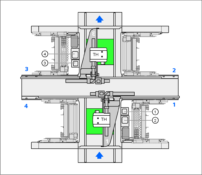
Fig. 7.3 - 2 Position of the component vision cameras for the TwinHead on the HF placement machine
(1) Assembly position for the CO vision camera (stationary, P&P (type 20) 8 x 8), location 1
(2) Assembly position for the CO vision camera (stationary, P&P (type 22) 50 x 40), location 1
(3) Assembly position for the CO vision camera (stationary, P&P (type 20) 8 x 8), location 3
(4) Assembly position for the CO vision camera (stationary, P&P (type 22) 50 x 40), location 3
7 Station extensions User manual SIPLACE HF series
7.3 Component camera for the TwinHead, FC camera Software Version SR.50x.xx 01/2006 US Edition
320
7.3.1.3 Position of the component vision cameras for the TwinHead on the
HF/3 placement machine
7
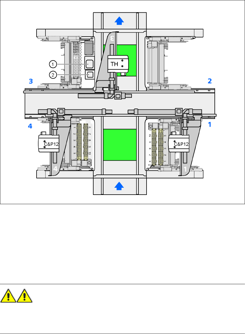
Fig. 7.3 - 3 Position of the component vision cameras for the TwinHead on the HF/3 placement machine
7
(1) Assembly position for the CO vision camera (stationary, P&P (type 22) 50 x 40), location 3
(2) Assembly position for the CO vision camera (stationary, P&P (type 20) 8 x 8), location 3
7.3.2 Safety instructions for the TwinHead component cameras during
a placement head change
WARNING 7
When the placement head is changed from the TwinHead to the Collect&Place head, the Twin-
Head's component vision cameras (stationary, P&P, type 22, 50 x 40, and type 20, 8 x 8) must be
removed, otherwise the Collect&Place head will collide with the camera housings.