00193922-03.pdf - 第150页
3 Technical data User manual SIPLACE HF series 3.12 PCB single conveyor Software Vers ion SR.50x.xx 01/2006 US Ed ition 150 3.12 PCB single conveyor The placeme nt machine is suppli ed with a single PCB con veyor as stan…
User manual SIPLACE HF series 3 Technical data
Software Version SR.50x.xx 01/2006 US Edition 3.11 Vision modules
149
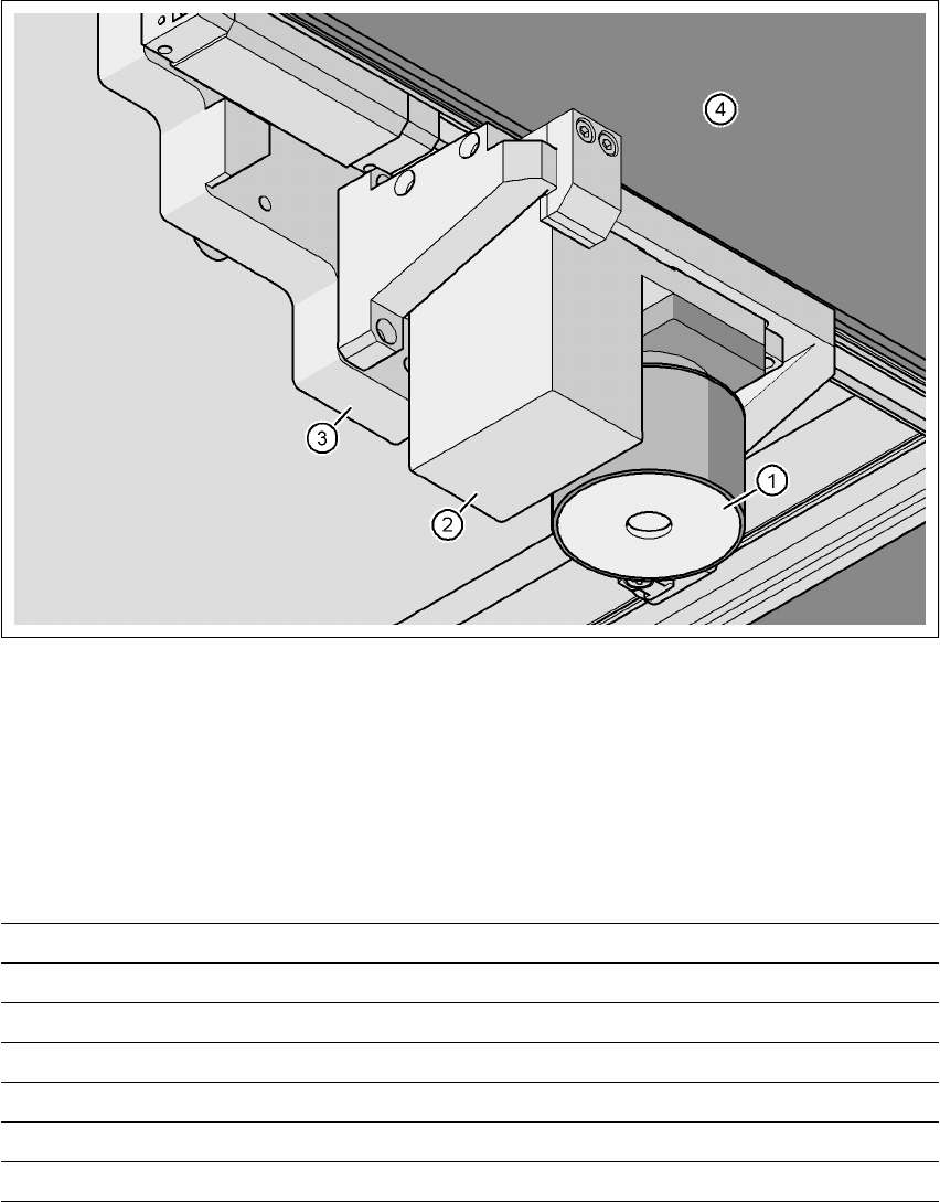
3.11.4 PCB vision camera, standard (type 5)
3.11.4.1 Position
3
Fig. 3.11 - 5 PCB vision camera, standard (type 5) on the gantry - view from below
(1) PCB camera lens and illumination
(2) Camera amplifier
(3) Head mount
(4) Gantry
3.11.4.2 Technical data
PCB fiducials Up to 3 (subpanels and multiple panels)
Local fiducials Up to 2 per PCB (may be of different types)
Library size Up to 255 fiducial types - system fiducials ≥ 249
Image processing Geometric alignment
Method of illumination Front-lighting
Detection time per fiducial/bad fiducial 0.4 s
Field of vision 5.7 x 5.7 mm²
3 Technical data User manual SIPLACE HF series
3.12 PCB single conveyor Software Version SR.50x.xx 01/2006 US Edition
150
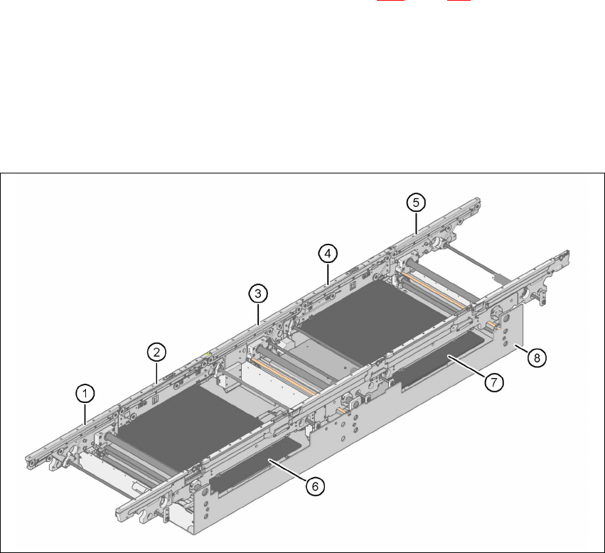
3.12 PCB single conveyor
The placement machine is supplied with a single PCB conveyor as standard. The dual PCB con-
veyor is available as an option from the factory (see Section 3.13
, page 153). The left or the right
side of the PCB conveyor can be used as the stationary side, as required. 3
The conveyor belts are driven by DC motors. There is a lifting table for clamping the PCBs in
each processing area. The PCB conveyor width can either be set from the user interface or pre-
set in the placement program. 3
3.12.1 Structure
3
Fig. 3.12 - 1 Structure of the PCB single conveyor
(1) Input conveyor
(2) Processing conveyor 1
(3) Intermediate conveyor
(4) Processing conveyor 2
(5) Output conveyor
(6) Lifting table 1
(7) Lifting table 2
(8) Assembly trough

User manual SIPLACE HF series 3 Technical data
Software Version SR.50x.xx 01/2006 US Edition 3.12 PCB single conveyor
151
3.12.2 Technical data
3
3.12.3 Description of the functions
For placement, the PCB is clamped from below. The distance between the top of the PCB and
the placement head thus remains unchanged for each PCB, and is no longer dependent on the
thickness of the PCB. The placement rate is thus also independent of the PCB thickness. The
PCB fiducial centering can also be optimized. Since the distance between the PCB surface and
the PCB camera remains the same, the PCB camera is always focussed on the PCB surface
with the same sharpness. The PCB fiducial contours are optimally mapped on the CCD chip of
the PCB camera. 3
The width of the circuit board conveyor is set and monitored by an integral control circuit. It can
be selected by calling up the program. The control circuit then actuates the stepping motors until
the desired width is reached. The width adjustment is therefore independent of other machine
components. 3
Fixed conveyor side Right or left
PCB format
Standard (L x W)
"Wide board" configuration
"Long board" option
50 x 50 mm² to 450 x 450 mm² (item no. 00119625-xx)
50 x 50 mm² to 450 x 508 mm² (item no. 00119629-xx)
50 x 80 mm² to 610 x 508 mm² (item no. 00119672-xx)
PCB thickness
Standard 0.3 mm to 4.5 mm ± 0.2 mm
(thicker PCBs available on request)
Max. PCB warpage Up: 6 mm - PCB thickness
Down: 0.3 mm + PCB thickness
PCB weight Max. 3 kg
Clearance on PCB underside
Standard
Option
25 mm ± 0.2 mm
Max. 40 mm ± 0.2 mm
Component-free PCB handling edge 3 mm
PCB changeover time < 2.5 s
PCB positioning accuracy ± 0.5 mm
PCB transport height 830mm ± 15mm (standard)
900mm ± 15mm (optional)
930mm ± 15mm (optional)
950mm ± 15mm (SMEMA: optional)
Type of interface SMEMA / SIEMENS
Bad fiducial detection Possible
Automatic width adjustment Possible