00193922-03.pdf - 第207页
User manual SIPLAC E HF series 4 Setting up and commissioning Software Vers ion SR.50x.xx 01/2006 US Edition 4.4 Setting up the placement machine 207 4.4.1 1 I nstalling the computer unit on HF and HF/3 4.4.1 1.1 Compute…
4 Setting up and commissioning User manual SIPLACE HF series
4.4 Setting up the placement machine Software Version SR.50x.xx 01/2006 US Edition
206
4.4.10.7 Installing the "bottom" hand guard
The machines from the HF series are supplied with just
one
"bottom" hand guard. If the machines
are installed within a line, then no hand guard is required between immediately adjacent output
and input conveyors.
WARNING
Always fit the "bottom" hand guard (item no. 03003432-01) on the input side of the
first
place-
ment machine and on the output side of the
last
placement machine of a line using 4 hexagon
socket head screws M4x12. This will prevent your personnel reaching into the machine without
authorization.
4
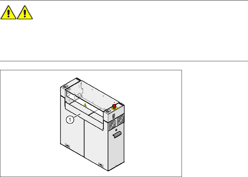
Fig. 4.4 - 18 Fitting the "bottom" hand guard on the PCB input side
(1) "Bottom" hand guard, item no. 03003432-01
User manual SIPLACE HF series 4 Setting up and commissioning
Software Version SR.50x.xx 01/2006 US Edition 4.4 Setting up the placement machine
207
4.4.11 Installing the computer unit on HF and HF/3
4.4.11.1 Computer unit - Electrical connection points
4
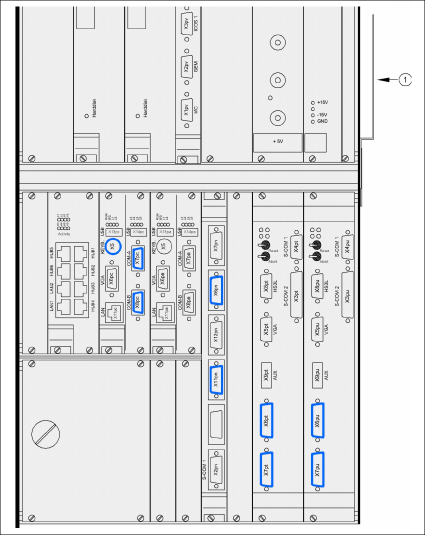
Fig. 4.4 - 19 Computer unit, front panel - Connecting the plugs
(1) Cable guide plate
Camera 2/4 Camera 1/3
Camera 2/4 Camera 1/3
CAN bus 2 CAN bus 2 CAN bus 1 CAN bus 1
4 Setting up and commissioning User manual SIPLACE HF series
4.4 Setting up the placement machine Software Version SR.50x.xx 01/2006 US Edition
208
4
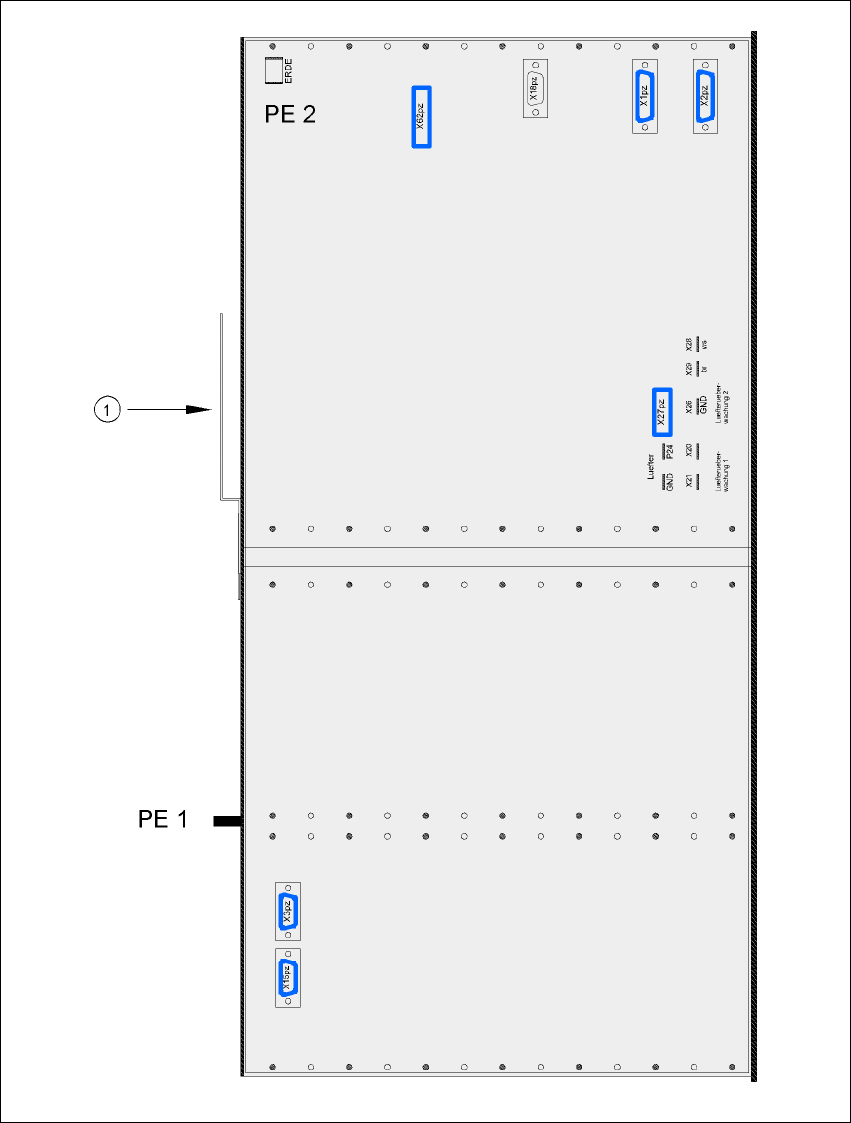
Fig. 4.4 - 20 Computer unit, back panel - Connecting the plugs
(1) Cable guide plate